Cutout
The modeling of various web cut-outs is currently available for welded I or H type cross-sections. Other types of sections will be available later. The effect of the cut-out is taken into account during analysis and design if the finite element of the member is shell, where the cutouts will be automatically included in the mesh during the finite element division. Analyzing with normal 7DOF beam finite element these objects are neglected.
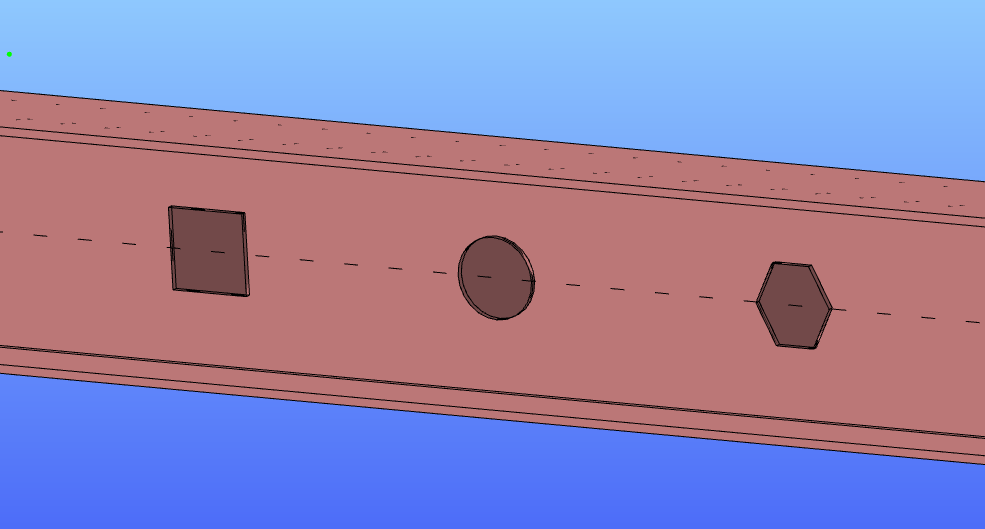
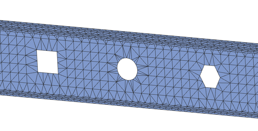
Creating cutouts
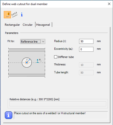
Cut-out can be placed on the webs of welded I or H sections, regardless of whether the member is set as a normal 7 DOF member or a shell element. The command can be found on the Structural members tab. Executing the command, the dialog window shown below will appear where three types of cut-outs can be defined and placed as described below.
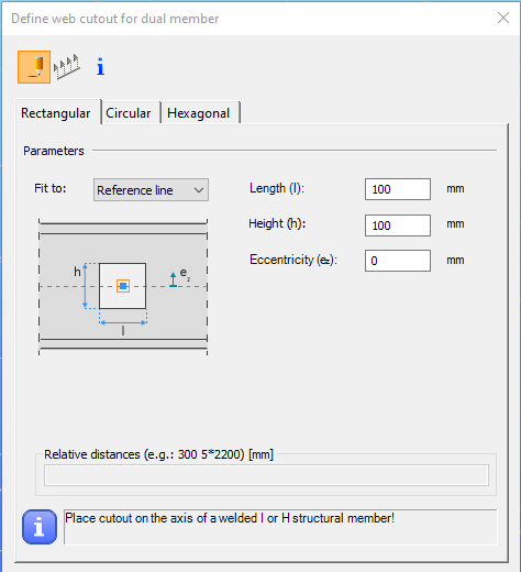
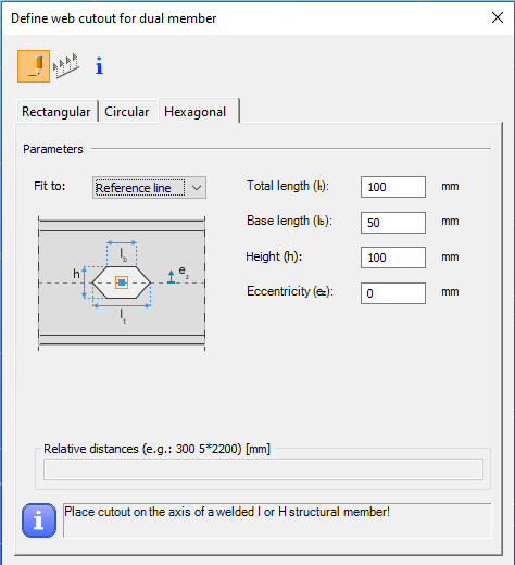
The usual placement options are available at the top of the dialog window:
the cut-outs can be placed individually by clicking on the reference line of the member,
or by multiple placement with relative distances interpreted in the member local coordinate system.
The properties of other cut-outs can get and used for new definitions as well.
In the Parameters section, the reference line of the cut-out can be defined on the left side of the window (Fit to). The figure shows the selected reference line below the drop-down box. The location of the object can be specified relative to the:
- reference line of the member,
- middle line of the web,
- top flange,
- bottom flange.
The selected option not only defines the cutout's reference object but also determines the axis. It is always placed perpendicular to the selected reference object.
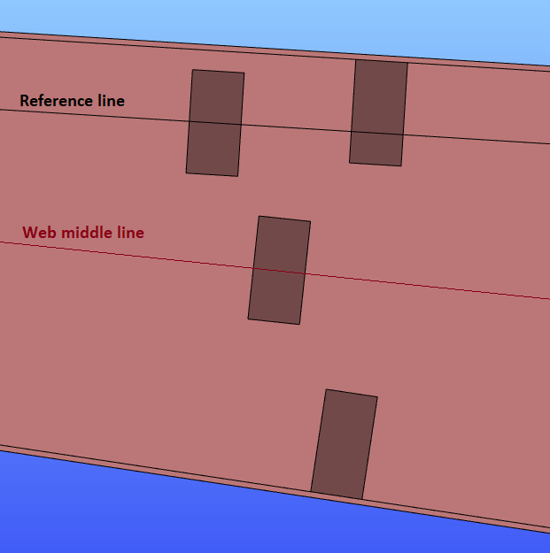
On the right side of the dialog window, the parameters can be entered according to the chosen geometry. Eccentricity can also be set for all types. For the circular cut-outs also a stiffener tube can be defined at the same time.
After specifying all the parameters the cutout can be placed on the members:
- one-by-one clicking on the member's reference line, or
- specifying a set of cutouts at the bottom of the dialog window, all the objects can be placed with one mouse click on the reference line of the member.
Analysis and design
Analysis
The effect of the cutouts is only taken into account during analysis if the finite element type of the member is set to shell, where the cutouts will be automatically included in the mesh during the finite element division. Analyzing with a normal 7DOF beam finite element, these objects are neglected.
Design
Cutouts are not considered in the design verifications at the moment.