Frame corner wizard

The Frame corner wizard is an optional function for modeling and calculation of the corner regions of structural models more realistically considering the overlapping of connected members. The function automatically identifies the corner zones and applies special treatment for the geometrical modeling, buckling analysis, plastic analysis, and global checks.
The main mechanical background is that these – generally stiffened – corner zones have usually significantly different behavior than the connected beam members. Since these zones are very short the behavior is influenced dominantly by the shear effect while the connected members have beam-column behavior with a dominant bending effect.
The function can be applied to member continuities that may be either continuous or semi-rigid (with the user specifying the end stiffness), ensuring that the behavior of the corner region can be reliably evaluated.
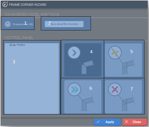
Functions of the frame corner wizard dialogue:

#1 - With the button frame corner recognition can be turned on, and off: By turning on frame corner recognition, frame corner definition can be started. Already defined frame corners can be turned off by clicking the button, and turned on again if it is desired.
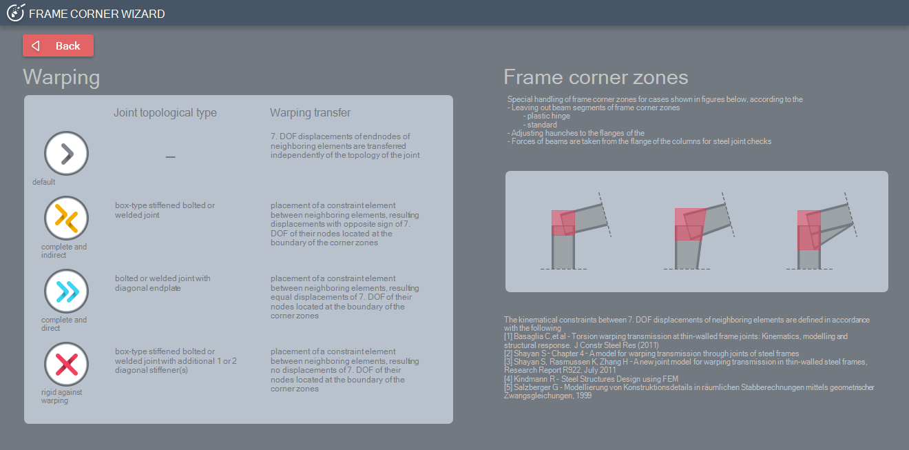
#2 - With the more about the function button, a new panel will open, where detailed information about the function is available.
#3 - Displays the model portion tree, in which it can be decided that what type of frame corner should be applied on which portion. It is important to note, that special frame corners (#5, #6, #7) can only be placed on model portions. The default frame corner type can be applied to the whole model. To place a special frame corner, it is necessary to select a model portion, and then with a click on a type of frame corner and on the Apply button, the frame corner will be placed on the model.
#4 - Default frame corner: 7. DOF displacements of end nodes of neighboring elements are transferred independently of the topology of the joint
#5 - Box-type stiffened bolted or welded joint: Placement of a constraint element between neighboring elements, resulting in displacements with opposite sign of 7. DOF of their nodes located at the boundary of the corner zones.
#6 - Bolted or welded joint with diagonal endplate: Placement of a constraint element between neighboring elements, resulting in equal displacements of 7. DOF of their nodes located at the boundary of the corner zones.
#7 - Box-type stiffened bolted or welded joint with additional 1 or 2 diagonal stiffener(s): Placement of a constraint element between neighboring elements, resulting in no displacements of 7. DOF of their nodes located at the boundary of the corner zones.

After clicking on the Apply button the program detects the overlapping zones of the members in the identified connection nodes including occurrent eccentricities, haunches, or tapered members.
The member segments inside the overlapping zones are separated and handled specifically:
- Geometry: the haunch is started at the end of the truncated member (at the end of the overlapping member segment). In this way, the real dimensions and position of the haunch are modeled.
- Buckling analysis: the finite elements belonging to the beam segments inside the overlapping nodes are left out from the buckling analysis (as it would be an unselected model portion). The reason is that in this zone member buckling cannot occur, and the effective buckling lengths of the members actually start outside of this zone
- Plastic analysis: the plastic hinges cannot be formed inside the corner zone. Accordingly, the plastic hinges are formed at the theoretically exact positions (for instance on the column below the haunch) and not in the connection node where the “virtual” bending moment is the highest
- Global checks: the global checks (including section and stability checks) are performed only for the member parts outside of the corner zone. In this way, the “virtual” peaks of the bending moments at the connection nodes inside the corner zones (which has no real mechanical meaning) are left out from the design checks and members are checked for the real, considerably bending moment (and the corresponding other internal force) values.
- Connection design: similarly to the earlier point the design bending moment and shear force values for the connection design are taken from the end of the truncated members where a beam-to-column connection is applied to the connection node where corner zone is defined.