Link elements
Link elements connecting elements that are not directly connected to each other. Three types of link elements can be used in Consteel:
Link
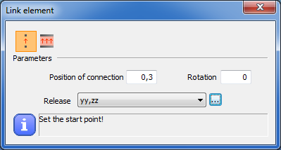
Link element () can be used to connect elements that are not directly connected to each other.
Parameters of the link element can be defined in the middle part of the dialog:
- Position of connection: this parameter defines the place where the continuity acts in the percentage of the length of the link element. Value can be between 0 and 1
- Rotation: rotation value defines the angle of the link element in degrees
- Release: predefined releases can be assigned to the specified position. If a new release type is needed the Release dialogue can be called by pressing the button next to the combo
There are two different types of link element.
Connect two structural points ( )
)
This type of link element can be used to connect two structural points.
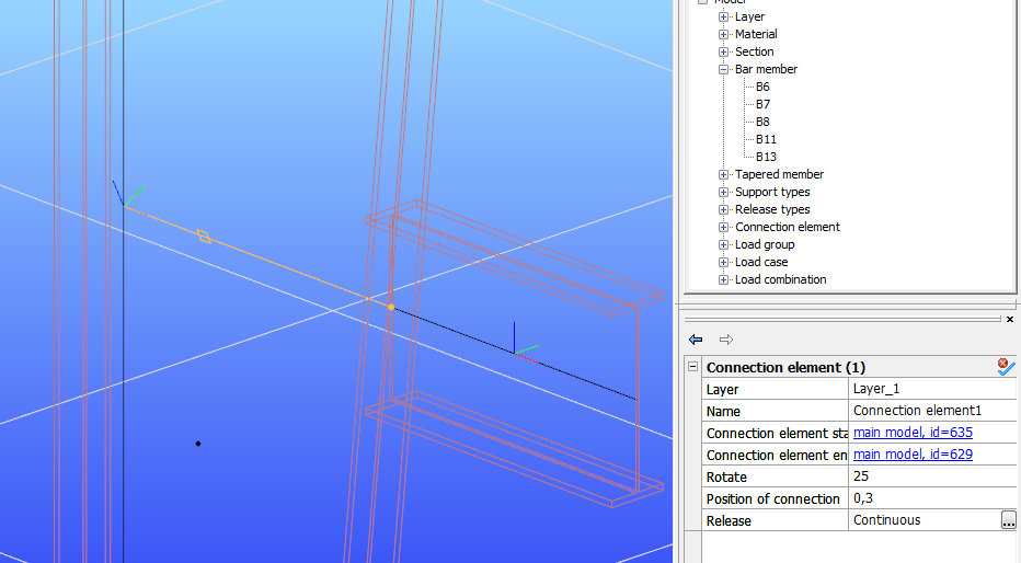
For example, if there is a cantilever on a relatively high tapered column (see image below) it is advisable to connect it not directly to the reference line of the column but with the link element. If it is connected this way the analysis and design results are more accurate and the modeling is more exact.
Connect two structural edges that are equal length and parallel ( )
)
Equal length and parallel edges and members can be connected with this kind of link element.
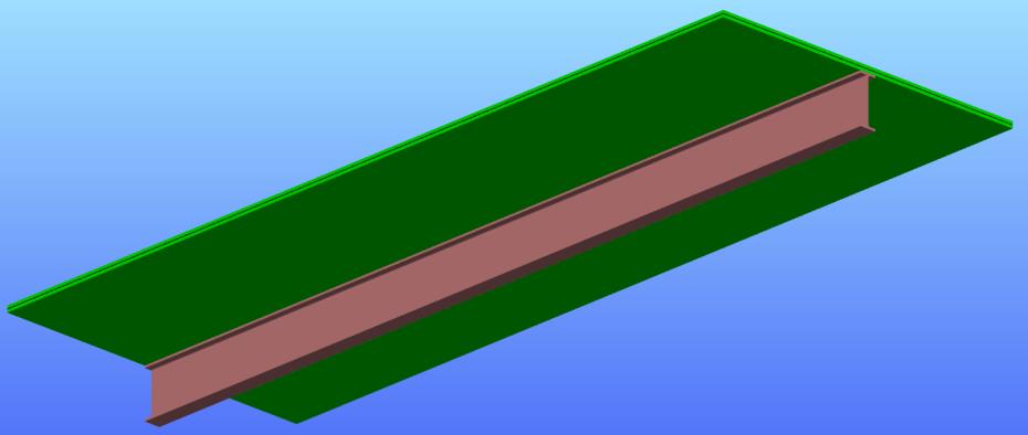
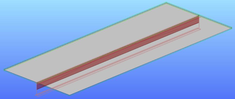
This type of link element can be used for example when connecting a slab eccentrically to a beam.
Smart Link
This type of link element makes it easier to handle geometric changes between connected members. The element follows the geometric changes (movement, rotation, section change) of the member on which it is placed (Main section). In addition, the other member connected to it (Connecting section) also follows the changes of the link element and thus the main section.
A typical application is a connection between the main beam and the purlin. With this object, we can place link elements at specific points on the main beam, to the endpoint of which we can easily connect members at a later time, based on the predefined eccentricity parameters. In the case of any change in geometry or profile, the smart link element follows the modification of the main beam, together with the member attached to it.
After starting the command, the Edit smart link dialog box appears:
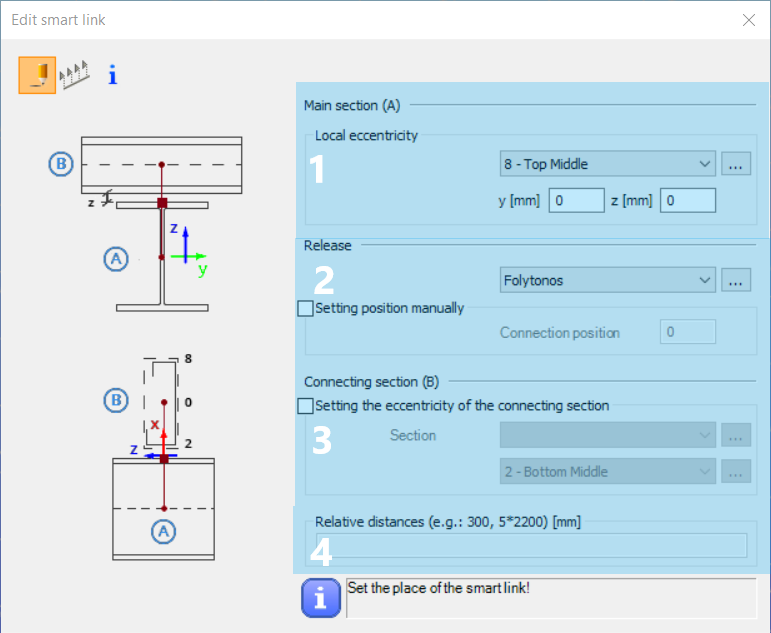
# 1 In the Main Section (A) field has to be specified the local eccentricity of the link element relative to a notable point on the main section.
# 2 In the Release field has to be set the continuity of the connection element by choosing from existing types or creating a new type. The connection point between the two members can be specified manually by selecting the "Setting position manually" checkbox or automatically by leaving it blank. In this case, the position will always be at the edge of the profile of the main section.
# 3 In the Connecting section (B) field, you can specify an eccentricity increment for the link element by specifying the connecting section. The program determines the length of the link element, taking into account the height of the section specified here and the section reference point.
There are two options for placing the smart link element(s).
With this function, the link elements can be placed one by one by clicking on a specific point on the member. The placed smart link element is always parallel to the Z axis of the member.
For group placement, you must first enter the placement distances measured from the start point of the member at the bottom of the dialog box (#4) and then click on a member to place it. If that cannot be placed on that particular member (e.g. because the member is not long enough), the program will not perform the operation and a warning message of "A smart link cannot be defined with these settings of the Main section!" will inform you.
It is important to know that the smart link elements cannot be copied together with the members currently. When copying a member containing smart links already placed on it, the smart links will not be copied together, but they have to be selected and copied separately.
Constraints
These types of link elements are special since these cannot be created manually, therefore there is no command icon on the menu bar. Constraints are generated automatically during the finite element generation if the following objects are present in the model:
- Frame corners with the help of the Frame corner wizard
- If any bar member is set to shell FE representation (see Superbeam for more info)
Constraint elements are represented with thick orange lines in the Finite element view of the model. Constraints transfer all or just some of the 7DOF beam element-like deformations from one node to another or from the beam to its shell element-based representation.
Frame corners
Constraints created in the frame corners transferring only the warping deformations between the beam and the column according to the type of the frame corner object. More information about the frame corner types: Frame corner wizard
Superbeam

The definition of which type of deformations are transferred depends on the value of the combobox in the property tree. The default value for constraints is Translational. The properties of the constraint elements can be accessed either by selecting the beam or selecting the constraint element itself on the Finite Elements view of the model.
In the first case constraints at both ends of the member can only be modified together, in the second case the constraint elements can be modified separately (only if the superbeam member is already converted to plates) .
The setting „Translational” results in coupling of displacements in all 3 global directions where the warping deformations of the 7DOF beam elements are also considered. The setting „Translational and rotational” will result in coupling additionally the rotations in all 3 global directions.