Geometry repair methods
The geometry repair methods are for automatic repair of geometric modeling errors. There are multiple different repair methods for different error types.
The geometric repair methods can be found on a button on the Geometry tab:
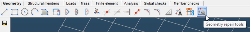
After clicking the button, a dialogue will appear from where the different repair methods can be accessed.
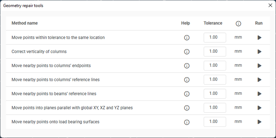
The methods can be run separately. All methods are operating on the entire model and will fix all errors meeting the criteria.
All repair methods are looking for errors on the level of model space points, and fix them by moving those points, in other words: changing the coordinates of these points. A separate message window reports how many points were modified after running any method. After moving a point, every model space object that references that point, also moves with the point.
Repair methods consider every point placed in the model space. This includes the points of every geometric, structural and loading related model space object. These objects include lines, polygons, columns, beams, plates, diaphragms, supports, links, load transfer surfaces, point loads, line loads, partial surface loads, point masses etc.
Dialogue controls:
- Tolerance - There is a modifiable tolerance value related to every method. The tolerance is the distance between model space points, within which the repair methods take effect.
- Help
 - Every help icon provides further details regarding the method or the dialogue element on mouse cursor hover and opens the related chapter of the online manual in a browser window if clicked.
 - Execution
 - Every method can be run with the rightmost button in its row.
Methods:
Move points within tolerance to the same location
Moves points within tolerance distance to each other to the same location. This location will be the location of one of these points. If there are more other points near one of these points (within 0.01 mm distance), then the final location is going to be the coordinates of the point that has the most other points nearby. In case of standalone points, the choice of the final location between the two points is random.
Correct verticality of columns
Makes almost vertical structural members perfectly vertical. A structural member is considered almost vertical if the difference between its start- and endpoints’ x and y coordinates are below the given tolerance.
Move nearby points to columns’ endpoints
Moves points within a spherical volume of tolerance radius from the endpoints of columns onto the endpoints. Every vertically positioned structural member is considered a column.
Move nearby points to columns’ reference lines
Moves points within a cylindrical volume onto the reference line of a column. The cylindrical volume is defined as a cylinder of tolerance radius around the reference line of a column capped by two parallel planes perpendicular to the reference line that are at tolerance distance from the endpoints towards the middle of the column. The line element that has an endpoint within this volume will be trimmed or extended such that it intersects the reference line of the column. In case of skew lines, the closest point on the element’s extended line will be perpendicularly projected onto the column’s reference line. Every vertically positioned structural member is considered a column.
Move nearby points to beam’s reference lines
Moves points within a cylindrical volume onto the reference line of a beam. The cylindrical volume is defined as a cylinder of tolerance radius around the reference line of a beam capped by two parallel planes perpendicular to the reference line that are at tolerance distance from the endpoints towards the middle of the beam. The line element that has an endpoint within this volume will be trimmed or extended such that it intersects the reference line of the beam. In case of skew lines, the closest point on the element’s extended line will be perpendicularly projected onto the beam’s reference line. Every not vertically positioned structural member is considered a beam.
Move points into planes parallel with global XY, XZ and YZ planes
Moves points that are almost in the same plane to be perfectly in the same plane.
All model space points are analyzed if they are almost in the same plane or not. Only planes that are parallel with the global XY, XZ or YZ planes are checked. A point is considered to be in the same plane as another point, if it is within tolerance distance in the direction perpendicular to the plane in question defined by the first point. A plane in this method is defined by its normal direction and the maximum and minimum coordinate in this direction, which comes from the maximum and minimum coordinate of all the points within this plane. The criteria to add another point to a plane is that it is within tolerance distance in the plane’s normal direction from the plane’s maximum and minimum coordinate. Therefore, it is possible for a plane to get “thicker” by every added point, and a plane can get arbitrarily “thick” by adding an arbitrary number of points.
Because of this, this method is only useful for models where the points are known to be in planes parallel to the global XY, XZ and YZ planes. The use of this method for models with slightly skewed planes is not recommended.
The final position of a plane is defined as the rounded whole millimeter coordinate of the plane’s maximum and minimum coordinate in its normal direction. All points that are considered to be in this plane are going to be moved to their parallel projection onto this final position.
Move nearby points onto load bearing surfaces
Moves points that are within tolerance distance to a load bearing surface onto the surface. The surface can be a load transfer surface or a structural plate. (The moved point’s local “z” coordinate in the surface’s local coordinate system is going to be 0.)