Create joint
Create joint without model
Joint models can be created without global model by clicking on the Edit Joint icon on the Structural members tab.

In this case the joint type, geometry and the loads need to be set manually. One of the advantages of Consteel, that in csJoint it is possible to handle several connections inside of a joint. By this, a large scale of customised joints can be designed. In the following, a creation of a beam-to-column joint will be demonstrated.
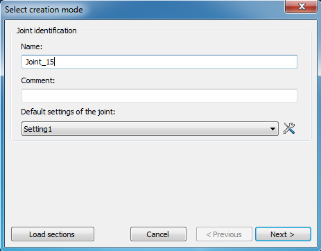
- Step 1 - Joint identification
After clicking on the Create button () on the top left corner the name of the joint must be given. Comment for the joint can be optionally given, and Default settings of the joint can be modified (see later in chapter Default joint settings ).
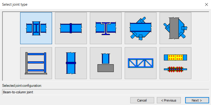
- Step 2 – Joint configuration
The type of the joint has to be defined on the next dialog. csJoint can handle great variety of joint types, which covers nearly the whole joint standard Eurocode 3 Part 1-8.
- Step 3 – Connections configuration
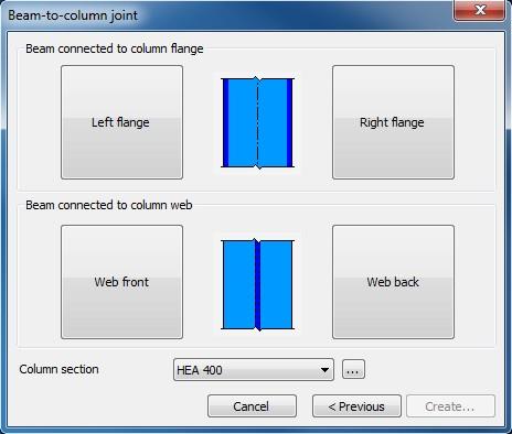
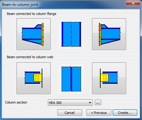
Here (picture above) it is possible to set connections both to the flanges and the web. For eligible list of connections, please see chapter Create joint. In this dialog, the section of the column is also has to be set. It can be chosen from the drop down menu, or loaded from the section administrator by clicking the three dot button ().
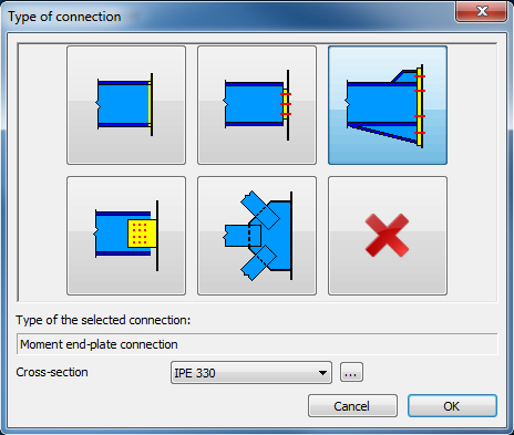
When setting a connection (picture above), the type and the cross section of the connected element has to be set. It can be chosen from the drop down menu, or loaded from the section administrator by clicking the three dot button (). For eligible list of connections, please see the Joint types chapter.
After the desired connections have been set (picture below), by clicking the Create button the joint will be created.
Joint loads can be given manually and the manipulations of the connection elements can be made as a last step.
For complete information about manipulating the connection, please see chapter Manipulating connections.
Create joint by model
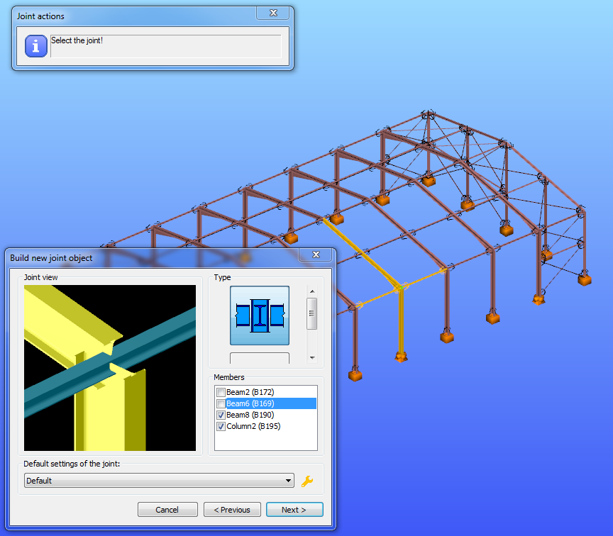
Creating joint by the model is simple and easy. Just click on the Create joint by model button and select the joint.

The members will be automatically identified and the possible connection types are offered. More detailed information regarding the Fictive Joint and Idea StatiCa Connection can be found in the Joint Export chapter. Here is possibility to remove some members from the identified connection by removing the appropriate tick.
Place joint in the global model
After creating the joint it is advisable to place it in the global model. There are two options to do this:
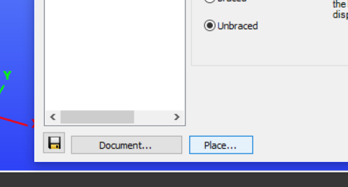
The fastest way of placing a joint, is to place it from the Joint details dialog directly, right after when it is been created. Place… button can be found at the bottom left corner of Joint details dialog (see picture below). By choosing it, it is possible to place the joint to several places by single clicks on the 3D structural model where the same geometry exists. By clicking End joint placement button (see picture below), loads will automatically imported from the model if analysis results are available.

The other way of placing a joint, is to use Place joint function, which can be found on the Structural members tab. This function is useful when more previously created joints have to be placed. One joint can be placed to several places in the model where the same geometry exists. After the joint is placed, csJoint automatically import the loads from the global model if analysis results are available.
It should be bear in mind that the settings in the csJoint module (profiles sizes, material grades, etc.) will not effect the 3D model. the changed values will be considered in the joint calculation only! The user has to way to keep the model consistent: 1. After modifying the connection the 3D model has to be changed accordingly, 2. Change the 3D model first run the analysis, redefine the connection.
Manipulating joints
No matter if a joint is created with or without model manipulating the joint is the same. Joint details appear in a new window where numerous settings can be made. In the following pages we would like to give an overview of the csJoint module using a beam-to-column connection as an example.
Select the joint from the tree structure on the Joint dialog, and press Details () button, or double click on the name of the joint.
Joint details dialog
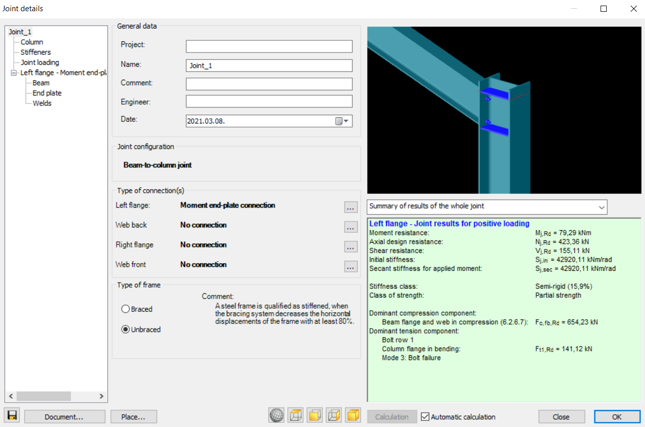
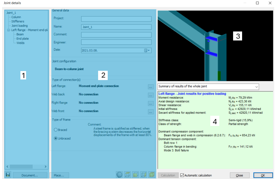
After the creation of a new joint, or opening an existing one for modification, the Joint details dialog appears, which can be separated into four parts. The window contains the general information about the joint: Joint name, project, engineer, date, etc. These properties will appear in the joint documentation and also useful to distinguish joints from each other.
-
(#1) The first part shows the tree structure about the joint: all components of the connection can be seen and selected.
-
(#2) On the second part, the selected component related information / properties can be seen and set: Joint name, project, engineer, date, etc. These properties will appear in the joint documentation and also useful to distinguish joints from each other.
-
(#3) The third part is the graphical window. Predefined views of the joint can be selected with the view tools:
-
(#4) The fourth part shows the results of the joint calculation. Calculation is automatically run when any changes take place and the Automatic calculation checkbox is clicked. If the checkbox is unchecked the calculation can be run with the Calculation button. In the pull down menu the type of the result visualisation can be set to three different types:
-
Summary for the whole joint
-
Summary for the selected connection
-
Detailed results of the selected connection
-
In the last two cases a connection must be chosen in the connection tree.
Documentation of the Joint can be started with the Document… button on the bottom left corner of the dialog.
Manipulating joint
Column
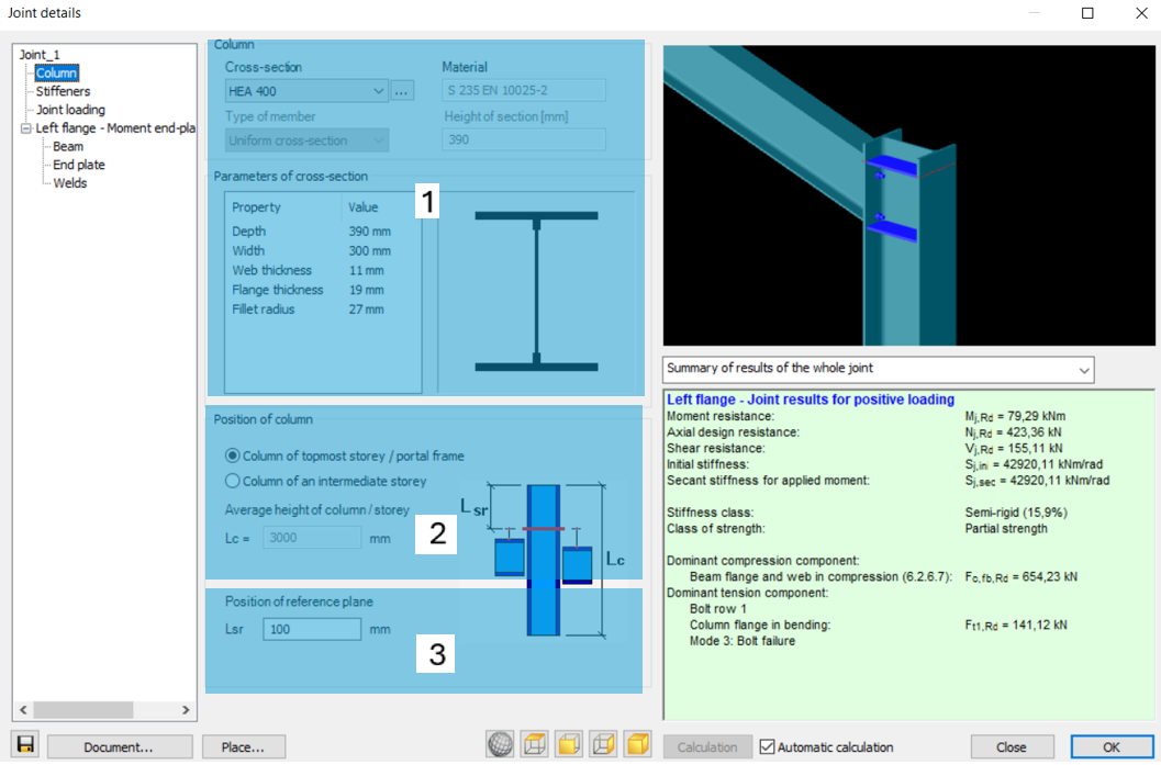
If the Column is selected in the connection tree, then column related properties of the connection can be set like the section size and material grade (#1). Setting the position of the column is also very important (#2). Furthermore the position of the reference plane is essential for the joint calculation. The image on the right gives a visual help about the meaning of ‘Lsr’ and ‘Lc’ variables.
Stiffeners
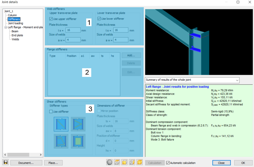
Stiffeners can be added if Stiffeners is clicked in the connection tree. Upper and lower stiffener plate properties can be seen in the #1 part of the image below. Additional web and flange stiffeners can also be defined (#2). In order to place shear stiffener in the joint click on ‘Use stiffener’ check box (#3). Bear in mind that the position of the stiffeners are measured from the reference plane of the beam, which can be set if the Beam is clicked in the joint tree (see below!).
Joint loading
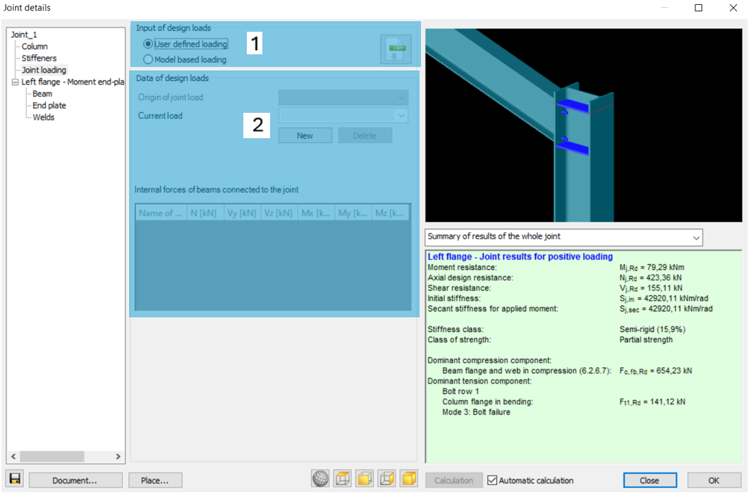
If Joint loading is selected, it is possible to choose from two options (#1). When “User defined joint loading” is selected, joint loads can be given manually by defining load cases, and internal forces (#2). If “Model based joint loading” is selected, csJoint automatically imports the internal forces from all of the combinations after the joint is placed in the modelling area.
Beam
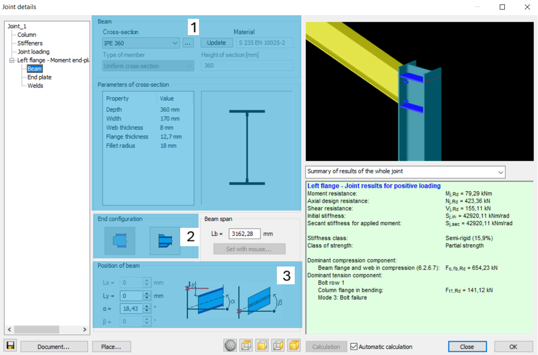
If the Beam is selected in the connection tree, then beam related properties of the connection can be set like the section size and material grade (#1). Beam end configuration can be set such as haunch (#2). Furthermore the beam span and position of the beam are essential for the joint calculation (#3).
End plate
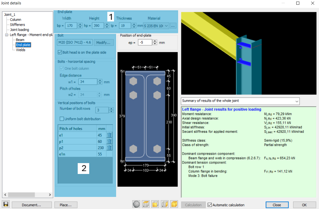
End plate properties (geometry, material) can be edited in the #1 part of the image below. Bolt properties can be seen on #2 part.
Welds
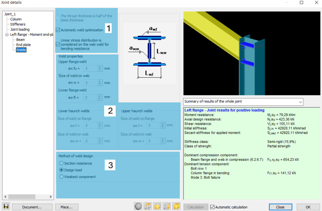
At Welds, it is possible to choose if welds should be optimized automatically or not (#1). If not, weld properties can be set manually (#2). Method of weld design also can be set in this window (#3)
Any changes made on the joint will take place either when pressing Enter or by clicking to another editable field on the window. If Automatic calculation is turned on and any changes take place then the calculation of the joint is automatically rerun. It can be turned off. In that case click on the Calculation button to run the calculation.
In the pull down menu the type of the result visualisation can be set to three different types: Summary for the whole joint, Summary for the selected connection, Detailed results of the selected connection. In the last two cases a connection must be chosen in the connection tree.
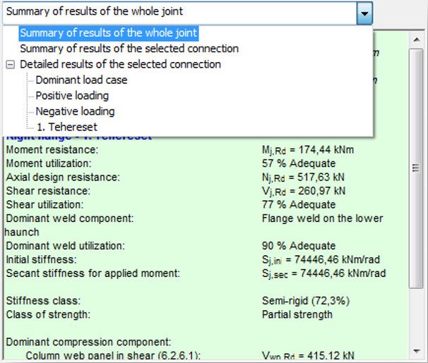
The result of the joint calculation can be seen in the highlighted part of the window. If the detailed result is selected then all the results of the necessary calculations can be seen according to the selected load combination or according to the dominant load case.
Default joint settings
The default joint setting like weld sizes, bolt diameter, etc. can be changed and saved.
Default joint settings can be changed and saved by clicking the Default joint settings () icon on the Joints dialog.
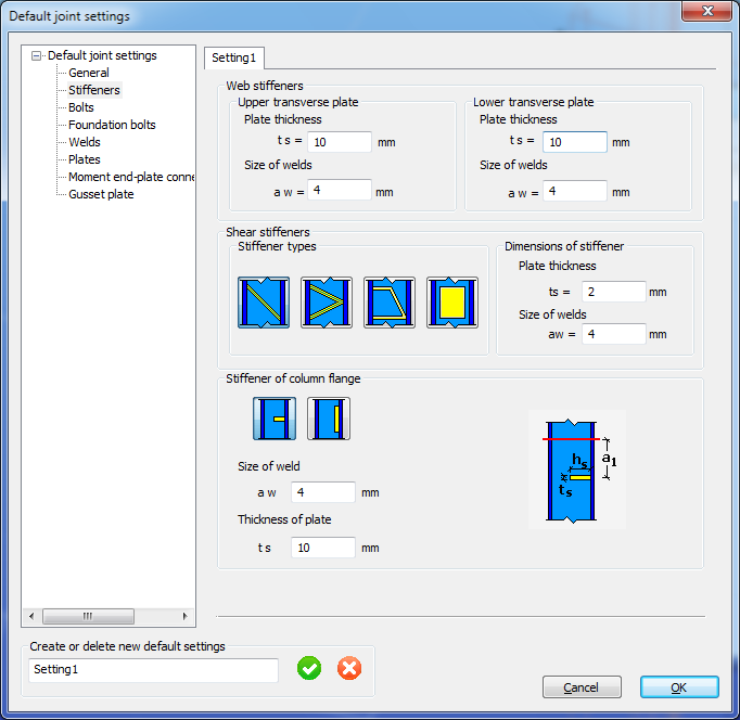
The default joint configuration file is saved to the Documents \Consteel folder as UserConfig.xml.