Seismic effect
Seismic effects can be created with the Seismic effect () function which can be found on the Mass tab. On the Seismic effect dialogue, all parameters can be set, which are required for the seismic analysis.
For the seismic effect creation, the existence of at least one pre-created mass combination and a response spectrum is required. To see how to define these, please go to chapter Masses!
A new seismic effect can be created by pressing the New button. More seismic effects can be created and saved. Change between different saved seismic effects is possible with the Name dropdown menu.
Options of the Seismic effect dialogue have been separated into two tabs:
- Seismic settings
- Additional effects
Seismic settings
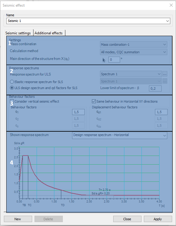
In the Settings (#1) panel, the main parameters of the seismic analysis can be set
- Mass combination: Choice of the used mass combination for the dynamic shape evaluation during the modal response spectrum analysis has to be done. The dropdown menu is automatically filled up with the pre-defined mass combinations. The seismic analysis will only be performed for the mass combination which is selected here!
- Calculation method: Choice of the calculation method to be used for the seismic analysis. To see the differences between each calculation method, please see the introductory part of this main chapter!
- Main direction of the structure from X: The main direction of the structure can be seen using the black arrow (
) tool, by clicking the start and end point of a vector in the modeling area. The other option is to set the angle between the main direction and the X-axis manually in the edit box with direct input. The direction, which is given will be the „1” direction, perpendicularly to this will be the „2” direction of the effect. The q1 and q2 factors correspond with these directions too.

On the response spectrums panel (#2), the response spectrum can be selected which will be used for the seismic analysis.
Handling of the response spectrums in ultimate and serviceability limit states can be the following:
- ULS response spectrum and use of qd factors: In this case choice of response spectrum (standard or user-defined) is possible only for the ULS checks. Deformations, which are necessary for the SLS checks are evaluated from the ULS results, using the qd displacement behavior factors
- Response spectrum for ULS and SLS limit state: Choosing the Elastic response spectrum for SLS option, different response spectrums can be set for ULS and SLS limit states. For ULS limit state, only standard or user-defined design spectrum, while for SLS limit state only standard or user-defined elastic response spectrum can be chosen from the dropdown menu
Clicking on the () button will bring up the spectrum definition dialogue, where parameters of a spectrum can be checked, or even new ones can be created (see chapter Creating response spectrums)
In the Behaviour factors (#3) panel, behavior and displacement behavior factors can be set for the main directions (1,2,z).
The number of adjustable behavior factors are depending on the type of the applied response spectrum(s):
| Behavior factor (q) | Displacement behavior factor (qd) | |
|---|---|---|
| ULS design spectrum and qd factors for SLS | Adjustable in case of standard response spectrum. In the case of user-defined spectrum, the spectrum containing it, cannot be adjusted | Adjustable |
| Different response spectrums for ULS and SLS limit states | Adjustable in case of standard response spectrum. In the case of user-defined spectrum, the spectrum containing it, cannot be adjusted | Cannot be adjusted |
Behavior factors besides the type of the spectrum, are dependent on the following options:
- Consider vertical seismic effect: If the option is turned on, vertical behavior factors can be set, and vertical seismic effects will be taken into consideration for the seismic analysis
- Same behavior in Horizontal XY directions: If the option is turned on, it is enough to define only one behavior parameter, it will be applied for both X and Y directions
At the bottom of the dialogue, in the Shown response spectrum panel (#4) the selected response spectrum –design or elastic- of the dropdown menu can be seen. By hovering the mouse over the points of the graph, its value will be displayed graphically.
Additional effects
On the Additional Effects tab of the Seismic Effect dialogue, the following settings can be adjusted:
- Accidental torsional effects: In the case of spatial 3D models, effects of the uncertainties of load placements causing torsional effects also have to be taken into account. Consteel calculates the effect automatically. For the calculation, storeys have to be defined, where the torsion effect is acting, and the eccentricity value, with which the mass points will be shifted.
- Second-order effect: Second-order effects have to be taken into account if the coefficient of the shift difference (θ) between the storeys is greater than 0,1. Consteel automatically calculates it and takes it into account. Storeys have to be pre-defined.
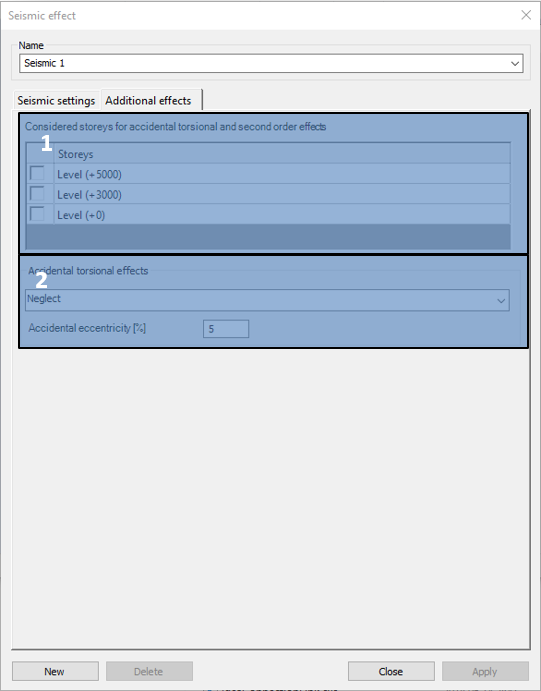
Considered storeys have to be chosen in the Considered storeys for accidental torsional and second-order effects (#1) panel. If there are storeys defined in the model (see chapter Portion Manager), they will be automatically loaded into the table. If the checkbox is turned on next to a storey, it will be taken into consideration during the seismic analysis.
When specifying the levels, it is important to know that Consteel takes the weights of the structure below the lowest level all of them to the lowest level by the torsional and second-order effects. This can be avoided by establishing a level 0 in the plane of the supports, so the weight distribution between the support and the first level will also be performed.

At the Accidental torsional effects (#2), consideration of the effect can be turned on or off. The following combinations can be chosen for the shift of the mass points:
- +eaX+eaY, - eaX-eaY: Mass points will be shifted both for positive and negative directions in the global X and Y directions with the given value, but not mixed. It is a simplification, and it is reducing the number of seismic combinations
- +eaX+eaY, +eaX-eaY, -eaX+eaY, - eaX-eaY: Mass points will be shifted both for positive and negative directions in the global X and Y directions, including mixed signs too, with the given value. It is the recommended way by Eurocode, but it increases the number of seismic combinations.
The value of the shift of the mass points can be given in the edit box with a percentage.