Reinforced concrete design
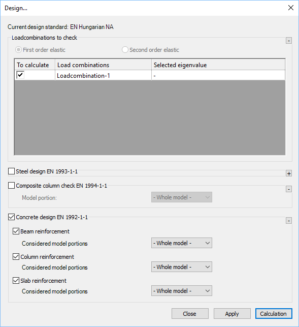
Design of concrete members are available at the Global checks tab. By clicking on the button, the Design… dialog will appear, where below the Steel and Composite design, the Concrete design EN 1992-1-1 panel can be found. On the panel, Beam reinforcement, Column reinforcement and slab reinforcement calculations are available. If the necessary input parameters for these calculations are available (cross sections, reinforcement data, design parameters and analysis results), the checkboxes are active, and choosing the desired item, Calculation can be initiated to obtain utilizations.

Required input parameters for concrete design are the following (see Chapter Reinforced concrete members for details):
-
In case of concrete beams and columns
-
Reinforced concrete cross sections with design option
-
Beam/column reinforcement object assigned to the concrete member
-
First or second order analysis results
-
-
In case of reinforced concrete slabs
-
Defined reinforcement schemes in the main directions
-
First or second order shell results
-
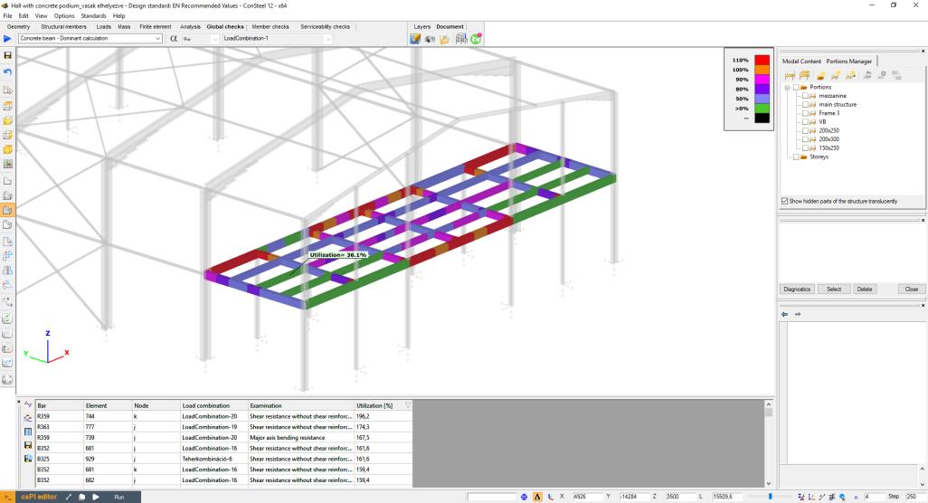
During the design, Consteel will perform the available standard checks according to EN1992-1-1 for all of the cross sections automatically. Cross sections with their dominant utilizations will be collected into the results grid, and will be shown using the color-coded visualization in the modeling area.

Results of the individual standard checks can also be obtained using the dropdown menu in the upper left corner of the design tab.
Reinforced concrete beam design
In case of concrete beam design, the following checks of EN1992-1-1 will be performed:
-
Longitudinal reinforcement
-
EN1992-1-1 9.2.1.1 (1) (9.1.n) formula - Minimum longitudinal reinforcement
-
EN1992-1-1 9.2.1.1 (3) formula - Maximum longitudinal reinforcement
-
EN1992-1-1 6.1 – Major axis bending
-
-
Shear reinforcement
-
EN1992-1-1 9.2.2. (6) (9.6.N) formula – Maximim stirrup distance
-
EN1992-1-1 9.2.2 (5) (9.5.n) formula – Minimum percentage of reinforcement
-
EN1992-1-1 6.2.2. (1) (6.2.a) and (6.2.b) formula – Shear resistance without shear reinforcement
-
EN1992-1-1 6.2.3. (3) (6.8) and (6.9) formula – Shear resistance with shear reinforcement
-
-
Interaction of shear and torsion
-
EN1992-1-1 6.3.2. (4) (6.29) formula – Resistance of inclined compression concrete bars
-
EN1992-1-1 6.3.2. (5) (6.31) formula – Required longitudinal torsion reinforcement
-
EN 1992-1-1 6.3.2. (3) (6.28) formula – Applied longitudinal torsion reinforcement
-
Reinforced concrete column design
In case of concrete column design, the following checks of EN1992-1-1 will be performed:
-
Longitudinal reinforcement
-
EN1992-1-1 9.5.2 (1) formula – Minimum diameter of longitudinal reinforcement
-
EN1992-1-1 9.5.2 (2) formula – Minimum longitudinal reinforcement
-
EN1992-1-1 9.5.2 (3) formula – Maximum longitudinal reinforcement
-
EN1992-1-1 5.8.3 and 5.8.8 – Biaxial bending
-
-
Shear reinforcement
-
EN1992-1-1 9.5.3 (1) formula – Minimum diameter of stirrup
-
EN1992-1-1 9.5.3 (2) formula - Maximum distance of stirrups
-
EN1992-1-1 6.2.2 (1) (6.2.a) and (6.2.b) formula – Shear resistance without shear reinforcement
-
EN1992-1-1 6.2.3 (3) (6.8) and (6.9) formula – Shear resistance with shear reinforcement
-
Reinforced concrete slab design
If there is a concrete slab placed in the model, with applied reinforcement in the main directions (see chapter 5.3), the slab reinforcement calculation option will be available in the Design… dialogue.
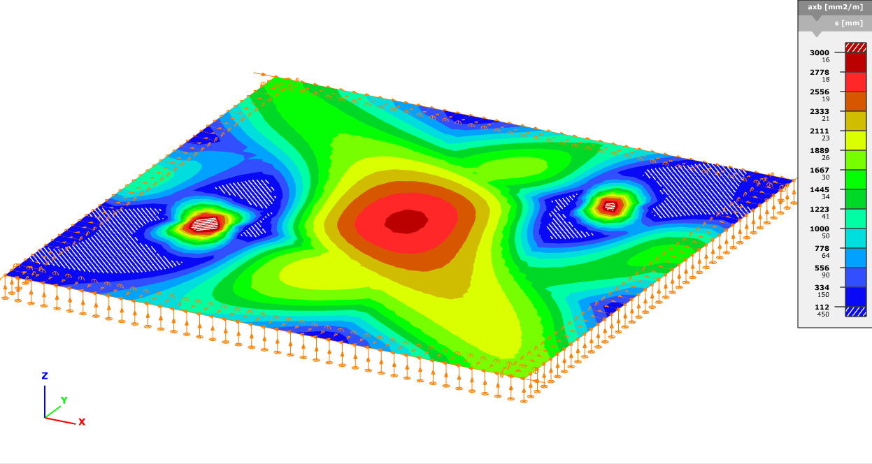
Result of the calculation is the required area of reinforcement [mm2/m] in each of the main directions, both in upper and lower positions. Change between the visualization of the directions is possible with the dropdown menu in the upper left corner. Results are represented with contour surface visualization:

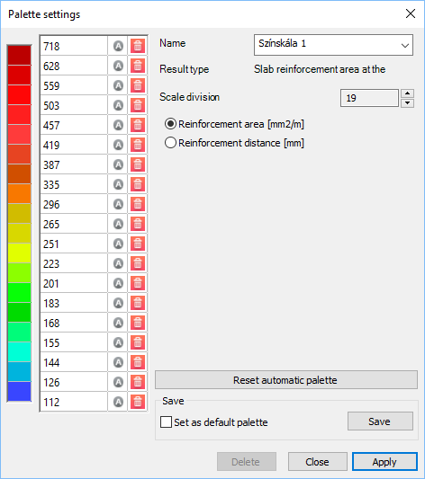
By clicking ont he colour palette with the right mouse button, properties (such as scale division, values of divisions) can be modified:

The result of the calculation, the contour surface with the colour palette itself can be exported into dxf form from File/Export menu (see Chapter 2.6).