Wind pressure simulation
![]() If a green checkmark appears next to the three-dot button, it indicates that the previous steps were completed successfully, allowing users to proceed with the wind simulation process.
If a green checkmark appears next to the three-dot button, it indicates that the previous steps were completed successfully, allowing users to proceed with the wind simulation process.
![]() The Info button provides detailed information about each step. Clicking it takes you to the documentation center for full guidance.
The Info button provides detailed information about each step. Clicking it takes you to the documentation center for full guidance.
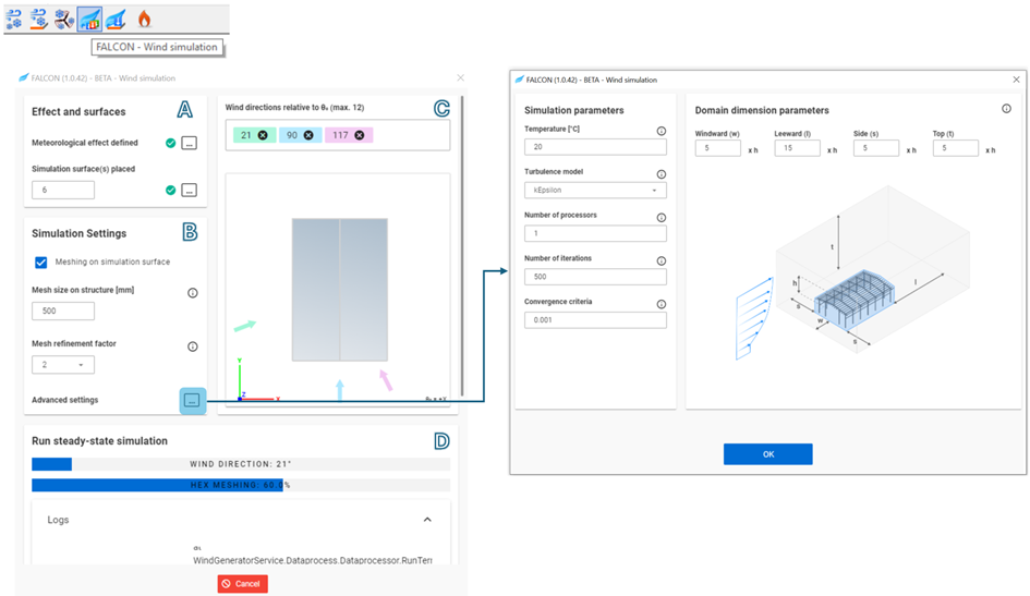
Use the FALCON-Wind Simulation button in the Loads tab to open the dialog.
This dialog is divided into four sections to guide users through the settings and simulation process:
A. Effects and Surfaces
-
Meteorological Effect: If not previously defined, users can navigate back to this setting by pressing the three-dots button.
-
Simulation Surfaces: The number below this section indicates how many simulation surfaces are currently placed in the model. If no surfaces are defined, use the three-dots button to navigate back and define them.
B. Simulation Settings
Mesh size on structure
-
Adjusts the mesh size applied to the simulation surface.
-
The average edge size of the generated meshes.
-
This parameter is used for the automatic generation of two independent meshes: the finite element mesh (FEM) generated by the plugin and the finite volume mesh (FVM) generated by the solver of the simulation. The FEM mesh generator was specifically developed for this plugin mainly for post-processing purposes. It produces a combined mesh of triangular and quadrilateral faces, independently of the wind direction, only for the building. It contains only planar faces, suitable for load creation. However, the results are projected to this mesh from the FVM, which contains polygonal faces and it is dependent of the wind directions, containing the whole simulation domain. The FVM is generated through an iterative refinement, therefore can produce mesh distortion, resulting non-planar faces, which are not suitable for mechanically correct load creation. During a simulation the results are stored only on the FEM.
-
The displayed recommended value is the minimum of two values: half of the shortest edge length among all the edges of the simulation surfaces or one-tenth of the smaller of the perpendicular and parallel dimensions of the building's bounding box.
Mesh refinement factor
-
The refinement factor (r) is used to increase the finite volume cell edge sizes (c) at the boundaries of the simulation domain, which are considered to be far enough from the building, therefore it is not necessary to calculate field values as densely as it is calculated around the building according to the mesh size on structure (s) parameter, which leads to quicker simulations. The formula to calculate the cell size at the boundaries is the following:
c = s × 2^r
-
The refinement is performed by cutting cells/finite volumes in half in each direction, i.e. a 3-D cell is transformed into 8 cells. In other words from the domain boundaries to the building in question the cell sizes are gradually decreasing to produce a refined mesh around the investigated building.
Meshing on simulation surface
- This setting affects only FEM generation. Disable it when working with buildings made up of multiple smaller simulation surfaces which can be considered as faces that together form a mesh and no extra refinement is needed.
Advanced Settings: Default settings are generally suitable, but advanced parameters can be adjusted if needed. Use the three dots button to modify:
Temperature
- The air temperature around the building to calculate kinematic viscosity required for simulation
Turbulence model
- The mathematical model applied to predict the effects of turbulence during simulation.
Number of processors
- The number of processors to run simulations in parallel.
Number of iterations
- The last iteration step, in case of non-convergence.
Convergence criteria
- The criteria of convergence for the calculated fields.
Show wind tunnels
- Domain dimension parameters- A set of dimensional multipliers. These values are used to multiply the height of the bounding box to obtain the actual dimensions of the finite simulation domain.
- Windward (w)
- Leeward (l)
- Side (s)
- Top (t)
C. Wind Directions
In this section, specify all wind directions in the XY plane relative to Θ₀, with a maximum of 12 directions at a time. After entering each new direction in the input box, press Enter.
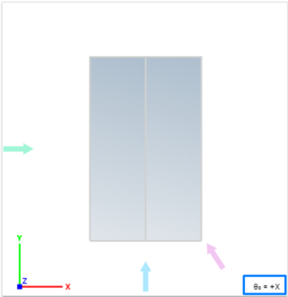
The Θ₀ direction is visible in the lower-right corner of the simulated structure top view, along with the wind simulation directions. The colored arrows indicate the simulated wind direction relative to the structure.
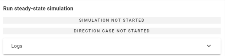
D. Run steady-state simulation
On the last sections the state of the simulation and direction can be observed:
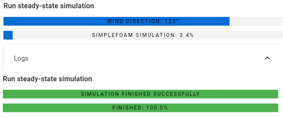
After pressing the Run button at the bottom of the dialog, two loading bars display the wind directions being simulated and their progress percentage.
While the wind simulations are running, Consteel remains fully functional, allowing you to continue working.
To monitor the simulation progress, open the Logs dropdown window. The simulation can be stopped at any time by pressing Cancel.