Composite design
Composite column design related functions can be found on the Global checks tab, beam design related function can be found on the Member checks tab.
Composite column design
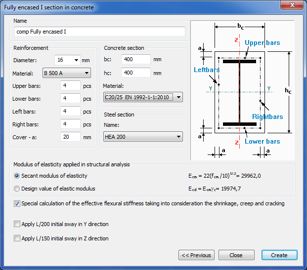
Cross-section of the composite columns can be evaluated on the global checks tab by clicking on the blue arrow. On the Design... dialog the Composite column design settings has to be chosen by the check box. Checks can be performed according to the first or the second order analysis and for the whole or a previously created portion model.

If the initial sways in the y and z directions were applied on the checked cross-section then the stability check of the composite columns can be neglected. Cross-section checks are enough.
Results
The results of the performed checks are demonstrated with graphical visualization and result tables (for the general functionality of tables used in Consteel see section General functions for tables).
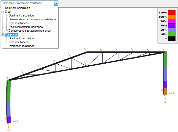
The shown results can be changed in the drop down menu.

When moving the mouse along the structural elements the result markers continuously appear showing the actual utilization.
The detail of the results can be seen in the Section module (see Chapter Section module). Section module can be opened directly from the Global checks tab to click on the proper cross section on the model area or in the result table with right click and select the Calculate section menu.
Composite beam design
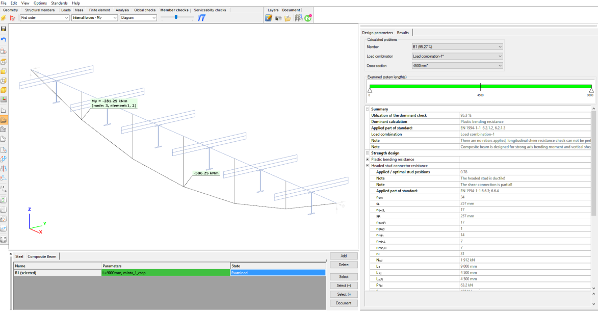
To run composite beam design go to Member checks tab and select Composite beam tab in the table at the bottom of the screen. Then select the composite beams and click on Add button. Now the selected beams are added to the table. Select the beam(s) from the list which you would like to design and click on Select (Select+) button. You can select which load combinations and first or second order results to use for the design. Then click on the Check button and the design will be performed.
Composite beam design in Consteel is carried out according to EN 1994-1-1:2010 standard.
The design bending resistance is determined using plastic theory according to 6.2.1.2 or 6.2.1.3 where the cross-section is in Class 1 or 2. The section class is determined acc. to 5.5.2. Class 3 and 4 cross-sections are not covered by Consteel composite beam design. The composite beam is checked for plastic bending, vertical shear, and shear buckling, crushing of the concrete flange and longitudinal shear at all the critical cross-sections. The critical cross sections are determined according to 6.1.1. (4). The following methods are not included in Consteel: non-linear resistance to bending (6.2.1.4.) and elastic resistance to bending (6.2.1.5.). The profiled steel decking is assumed not to contribute to the resistance.
Analysis model
In the analysis model the calculation of the effective width of concrete flange is based on the method defined in a previous chapter (in the dependence of the span and the distance between the shear studs in the cross section). Based on practice experiences, composite beams are usually created as two-pinned one span beams. Consteel can design composite beams with one span formation. In case of multi span beams, and where the tension is in the concrete flange, design can not be performed.
In the Analysis tab the analysis model is displayed.
Design of shear studs
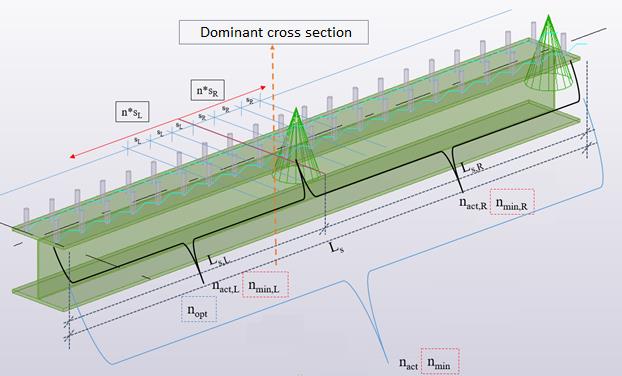
The allocation of the studs is plastic based, where the studs has to be distributed uniformly in both directions from the dominant cross section. The dominant cross section, where the bending is maximal, is located automatically.
If the number of shear studs is desired to be calculated automatically, Consteel willcalculate the bending resistance of the beam with the minimal required number of studs. Consteel will increase than the number of shear studs, until the bending resistance exceeds the acting bending on the beam.
The green section on the schematic figure below shows, where the optimal distribution of shear studs is calculated. The following parameters are evaluated for the examined part of the beam:
nopt: optimal number of shear stud positions along the dominant phase of the beam
nact: number of shear stud positions along the examined member
sL: shear stud distribution in the left direction from the dominant cross section [mm]
nact,L:number of shear stud positions in the left direction from the dominant cross section
sR: shear stud distribution in the right direction from the dominant cross section [mm]
nact,R: number of shear stud positions in the right direction from the dominant cross section

nstud: number of shear studs in one cross section
nmin: minimum number of shear stud positions along the member
nmin,L: minimal number of shear stud positions in the left direction from the dominant cross section
nmin,R: minimal number of shear stud positions in the left direction from the dominant cross section
Instead of using the automatic evaluation of the number of the shear studs, manual definition of the number of studs is available too. In this case, the software checks, if the distribution fits to the detailing rules, such as the minimal and the maximal distance between the studs. The number of the studs has to be given for the whole length of the beam. During the check of the beam, Consteel will uniformly distribute the studs along the member (In case of automatic evaluation of required shear stud numbers, non-uniform distribution is also possible).
Calculation of the utilizations of the shear studs are evaluated by the dividing the applied number of shear studs with the optimal number of shear studs (nact / nopt)

Shear buckling resistance of composite beams
The shear buckling resistance of the web is determined in accordance with section 5 and Appendix A of EN 1993-1-5:2006. The shear resistance contribution of the flanges is ignored.
Bending and vertical shear resistance
The influence of vertical shear on the bending resistance is ignored if the vertical shear force is less than the half of the shear resistance.
For Class 1 or 2 cross-sections, if the vertical shear force exceeds the half of the shear resistance, the reduced design steel strength is used to calculated the bending strength of the member as defined in 6.2.2.4 (2)
Lateral-torsional buckling resistance of composite beams
Lateral-torsional buckling of composite beams is not included.
Sheeting with ribs parallel to the supporting beam
The design shear resistance of studs is taken as the resistance of the studs in solid slab multiplied by the reduction factor as defined in 6.6.4.1 (2).
If the sheeting is discontinuous Consteel assumes that it is welded to the flange of the beam but the distance between two ribs (‘a’ parameter) can be set.
Sheeting with ribs perpendicular to the supporting beam
The design shear resistance of studs is taken as the resistance of the stud in the solid slab multiplied by the reduction factor as defined in equation 6.23, limited to the maximum value as defined in Table 6.2. While calculating the resistance of studs in solid slabs the stud ultimate tensile strength is limited to 450 N/mm2.