Steel design
Steel design related functions can be found on the Global checks and the Member checks tabs.
Global checks
Basics

The Serviceability Limit State Checks and the Ultimate Limit State checks
are both included in the Global Check tab.
The global checks run button initiates all the checks with the previously applied settings. This button is meant to be used when we don’t change the settings for the analysis and the load combinations, just in case of repeating calculations, for example when we change the section for an element.
Ultimate limit state checks
Cross-section and global buckling checks (according to the Section 6.3.4 (General method) of EN 1993-1-1) which are independent of any specific member parameter can be fully automatically evaluated.
As basic settings the analysis result type (first or second order) should be selected and the load combinations which should be evaluated.
Cross section check
Cross-section check can be done according to the EN 1993-1-1 6.2 or EN 1993-1-2 4.2 (if the combination contains fire effect).
Check can be performed for the whole model or partial model.
Used safety factor can be selected. If it is necessary γM1 can be used instead of γM0 by clicking on the checkbox.
If the model also includes cold-formed sections, their cross-sectional dimensioning according to EN 1993-1-3 can be performed only, if the check box on the Set Design parameters window is checked.
Stable length check
According to the Eurocode (1993-1-1 BB3), stable length check can be defined using the results of a plastic hinge analysis. During the calculation, the distance between the plastic hinge and the nearest lateral (Lub) or torsional restraint (Lm, Ls) is being compared with the calculated stable length of the corresponding plastic segment. If the stable length of a plastic segment is bigger than the distance between the plastic hinge and the lateral/torsional restraint, lateral torsional buckling of the member can be neglected.
During the stable length check, the following checks are performed by Consteel:
-
Automatic recognition of the plastic hinges on the structure
-
Searching for the nearest supports of each plastic hinges
-
Lateral restraint
-
Torsional restraint
-
-
Defining the distance between the plastic hinge and the nearest supports
-
Calculating the stable length (depending on the type of the support) for the plastic segments, between the plastic hinge and the nearest supports
On the elastic segments global stability resistance will be evaluated according to the General method of Eurocode.
Buckling check
Buckling check can be evaluated for steel structures according to the EN 1993-1-1 6.3.4.
To run the buckling check, it is required to have buckling analysis results.
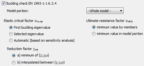
For the buckling check the following parameters can be set:
- Elastic critical load factor eigenvalue of the buckling analysis. It can be the first or the selected eigenvalue according to the design situation or can be automatically selected for each members based on the results of the sensitivity analysis.
Eigenvalue can be selected on the Analysis tab to click in the model area with right click.
- Ultimate resistance factor reciprocal of utilization calculated with characteristic resistances of axial force and strong axial bending dominant in terms of loss of stability. Value of the utilization can be considered by members or by the model portion.
- Reduction factor reduction factor for the slenderness. It can be determined from the minimum of (,) or from the interpolated value of (,).
Check can be performed for the whole model or partial model.
Results
The results of the performed checks are demonstrated with graphical visualization and result tables (for the general functionality of tables used in Consteel see section 1.4 General functions for tables).
The shown results can be changed in the drop down menu.
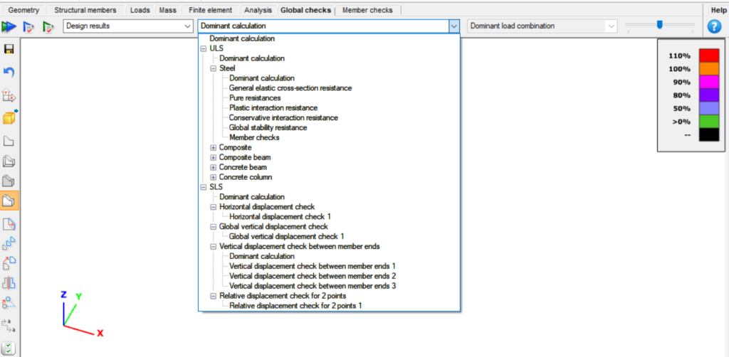
In the first dropdown menu, users can choose between Design results and Predesign parameters.
Design results
Under the dominant calculations, there are two subcategories: Ultimate Limit State (ULS) and Serviceability Limit State (SLS) design.
The ULS results are further subcategorized based on the materials and calculations used.
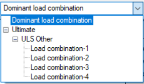
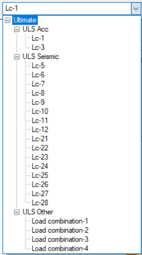
For the steel materials, not only the dominant results but also results from every load combination are saved and can be visualized with the help of the last dropdown menu:
The SLS checks are only listed by the selected check criteria. Each criterion has results for all the combinations, as well as dominant calculation.
The Predesign Parameters can be seen according to the 4 categories: Sensitivity, Fire, Secon- order concrete column internal forces and Slab reinforcement area.
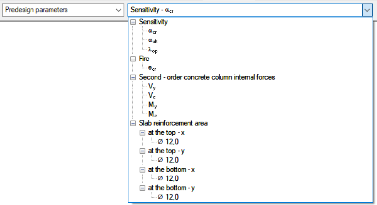
For parameters that are combination-related, such as sensitivity and second-order concrete column internal forces, the third dropdown menu is also available to choose the load combination to be investigated.
At the bottom part of the window, a table with the results will appear. It will display the relevant information according to the selected calculation criteria above.
For the Ultimate Limit State (ULS) calculations, information is displayed regarding the Bar, Element, Node, Load combination, Limit State, Examination, and Utilization. However, for the Serviceability Limit State (SLS) checks, the Bar and the Element are irrelevant.
By clicking on any cell in the table, a blue arrow will appear pointing to the element with the selected properties.
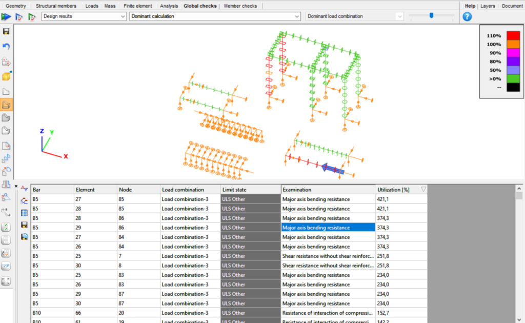
Users can calculate the section or select the whole member by right-clicking on a cell.

The ‘Calculate section’ brings automatically to the Section module.
It is possible to select all the chosen members by selecting multiple cells, even if they are not in the same column.

For more detailed information about the selection process, please visit the Selection page.
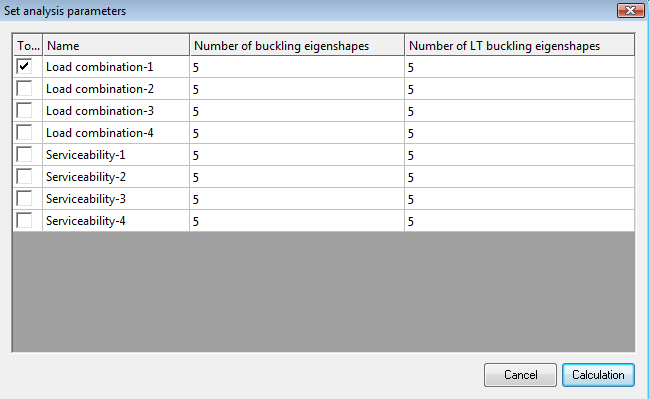
With a right-click on a load combination, an additional option appears: "Select only these load combinations for the Analysis" allowing users to repeat the analysis only with those combinations that require further investigation.

For some of the predesign parameters also exist result table:
- Sensitivity
- Fire

The right-click function on the cells operates similarly to the design results table.
Member checks
Basics
All steel member design related functions can be found on the Member design tab.
The following parts of the Eurocode 3 (EN 1993-1-1) can be evaluated:
6.3.1 Uniform members in compression
6.3.2 Uniform members in bending
6.3.3 Uniform members in bending and axial compression
Individual Member Design
To run steel member design go to Member checks tab and select Steel tab in the table at the bottom of the screen. First the members have to be selected and then added to the list. It can be performed by clicking on the Add button. After that one member has to be chosen and Select button is clicked.

If a member is selected, the corresponding row highlighted with green and analysis results are automatically loaded. Member design can be run if there is analysis result (first and second order) and cross check for the member. Same like in the analysis the type of the result view can be set by three drop down menus.
Special analysis can be run by clicking on the second icon (#1). Only one load combination can be selected at the same time. Buckling and lateral torsional buckling analysis is performed just for the selected member. If the normal force is negligible then no buckling analysis can be run. On the basis of these special analysis, Consteel can determine the factors (effective length factors, warping factor etc.) for the buckling and the lateral-torsion buckling design.
The next step is to choose the load combination and design type from the options: pure cases (strong axis buckling, weak axis buckling, lateral-torsional buckling) and interaction stability (interaction of buckling and lateral torsional buckling, interaction of buckling and bending, interaction of lateral-torsional buckling and bending). The dominant load combination is automatically selected and marked with a * symbol.
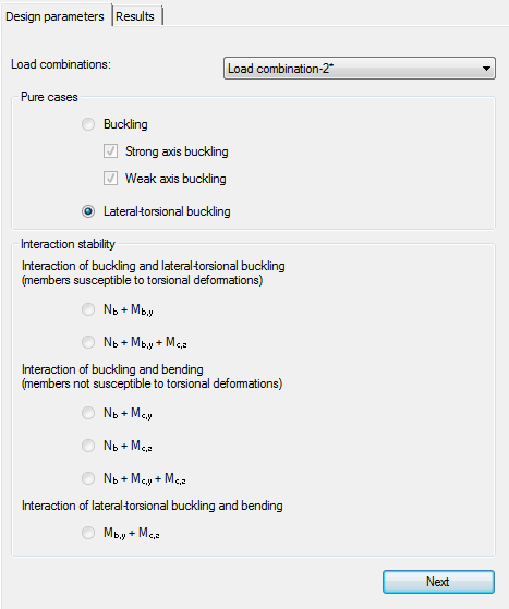
Depending on the member not all checks can be performed. If the normal force is negligible then strong or weak axis buckling design cannot be run.
If strong or weak axis buckling option is selected then first the design parameters has to be set. The program automatically identifies the supports which could have effect on the buckling check.
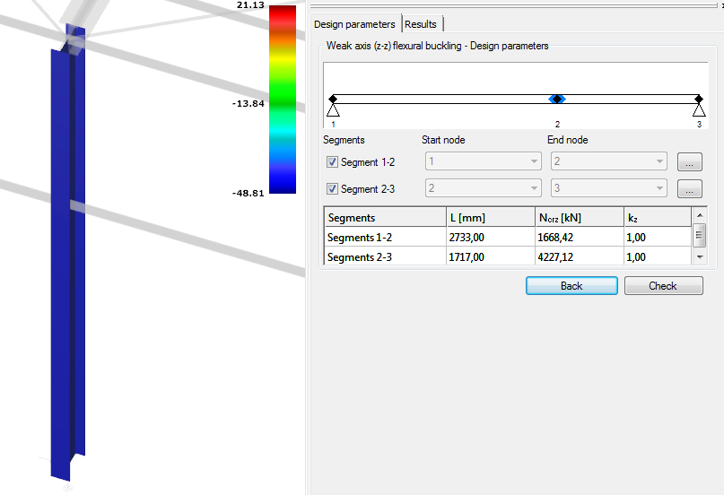
Among the supports the member is divided to segments. Segments can also be turned off in order not to calculate them during the analysis. The design parameters can be individually set for each segment by clicking on the three dots icon.
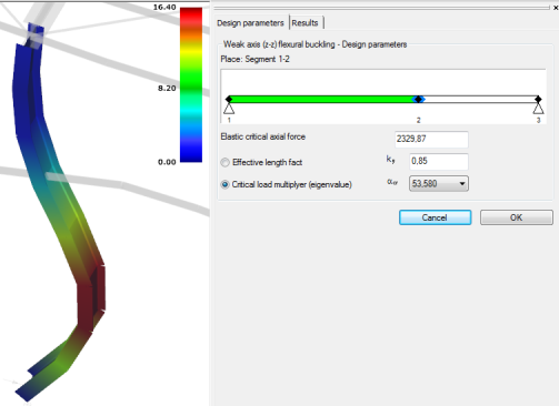
The actual segment is highlighted with green. There are two options to set the design parameters: set the effective length factor manually by typing in the appropriate value or by choosing the right critical load multiplier. The second option is possible if the special analysis has already been run. In both cases the elastic critical axial force is automatically calculated.
If all the design parameters has been properly set then design check can be performed by clicking on the Check button. Results will be displayed.
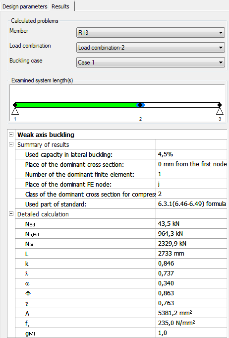
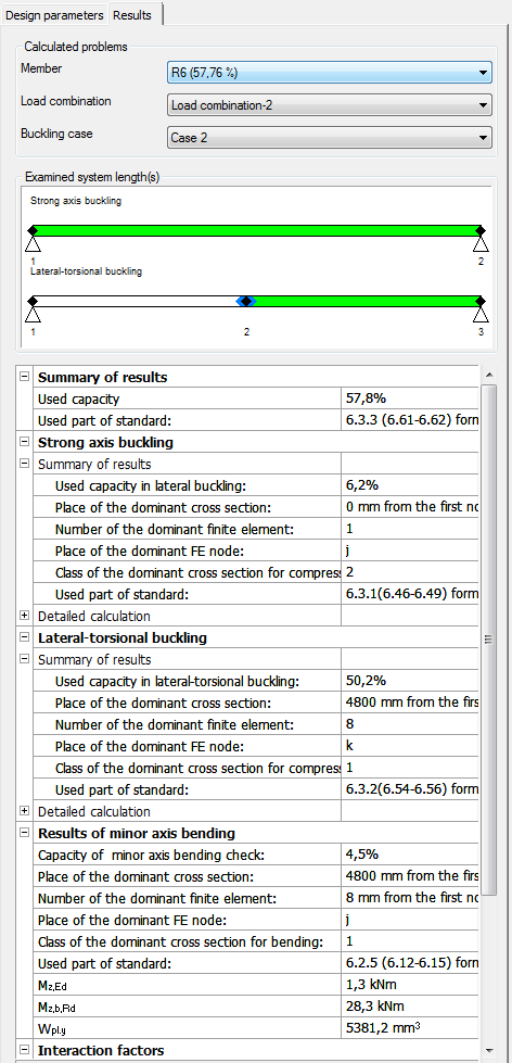
There are three drop down menus in order to view different results. The first one can be used to change member, the second one is to change load combinations and the third one is to change the buckling case. The corresponding case is highlighted with green in the image. A short explanation can be read in the bottom when any of the rows is selected.
Lateral torsional buckling design is more or less the same as the buckling design in Consteel usage, there are only small differences. New cases can be defined and unnecessary cases can be deleted. For each segment start and end node can be set.
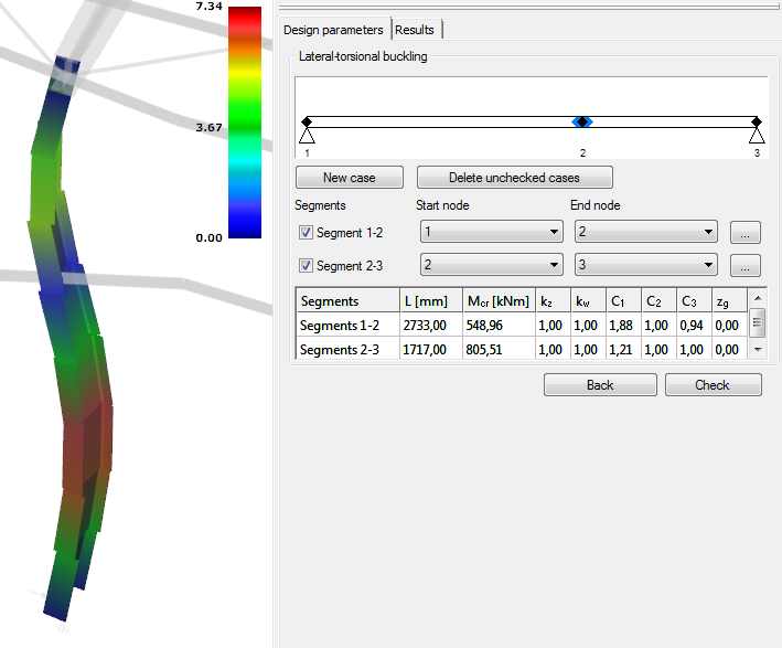
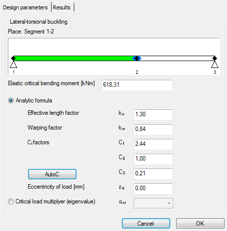
By clicking on the three dots button the design parameters can be altered. The elastic critical bending moment can be calculated from the analytic formula or from the critical load multiplier. When the first method is used the factors can be typed in or a special automatic C factor calculator can be used by clicking on the AutoC button. The second option is to choose the corresponding critical load multiplier from the list.
Interaction stability design goes through the steps of the pure cases.
After the check is made the state of the member in the list at the bottom changes to ‘Examined’ from ‘Unexamined’.
Member Group Design
By using the Select (+) button it is possible to select more members for the member design. Select (-) can be used for remove members from the selection. Member group design works nearly the same as individual member design there are just minor differences. No special analysis can be run in member group design therefore the critical load factor cannot be selected.
If the members are selected then the next step is to select the design type and set the design parameters, then click Check button similar to the individual member design.
For each load combination member design can be turned off. It is important to know that not all the design options can be run for all members in load combinations. It depends on the analysis result.
In the results tab the dominant member is automatically shown. The number next to the member number shows the capacity.
