Global imperfections

Three types of global imperfection can be applied on the model with the Global imperfection () function. Several numbers of imperfections can be created, but only one can be used for the analysis at the same time. Used imperfection can be set for the analysis at the Analysis tab’s Set analysis parameters dialog.
Notional Load
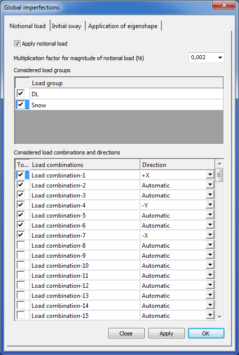
Initial imperfections can be taken into account by the application of notional loads.
On the basis of the selected load groups, the notional loads will be generated automatically in the selected load combinations. Direction of the notional loads can be defined automatically or can be set for every load combinations.
Multiplication factor for magnitude of notional load (Ni) can be selected from the dropdown menu, or can be type manually. This factor means how much percentage of the selected loads will be act as a notional load. Value can be between 0 and 1.
Pressing the Apply or the OK button the notional load will be created.
Initial sway
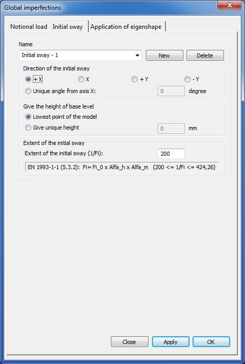
Initial sway can be set for the whole model.
With the New button several initial sway can be created or can be deleted by the Delete button.
To create an initial sway, the direction, height of base level and the extent of initial sway (1/Fi) have to be given.
Pressing the Apply or the OK button the initial sway will be created.
Application of eigenshape
Previously calculated buckling modes can be applied universally as a geometric imperfection for all of the load combinations. Even more buckling modes, as an imperfection case, can be easily superposed as one imperfection.
Apply eigenshapes
Previously performed buckling analysis is needed to apply an eigenshape as an imperfection.
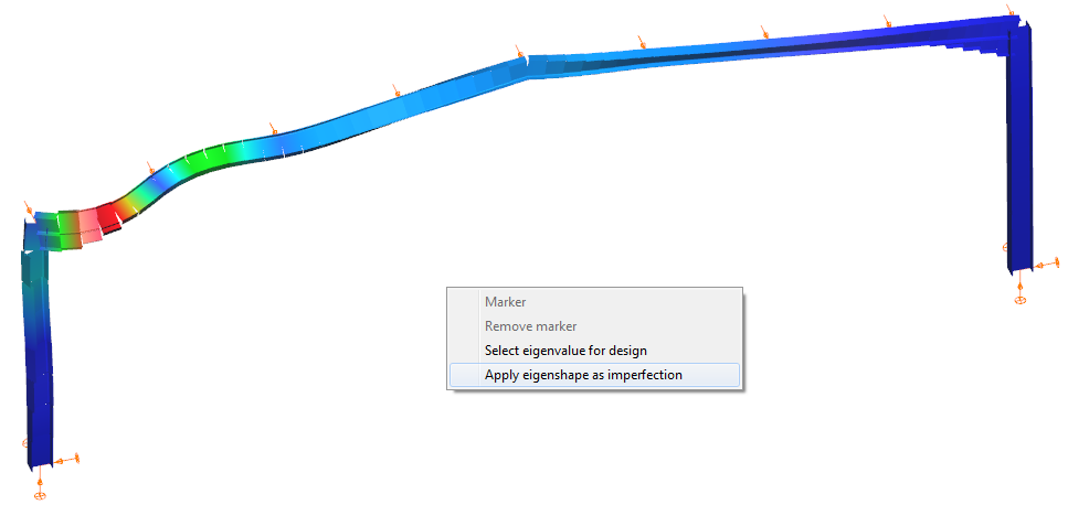
On the Analysis tab’s Buckling result view either calculated buckling mode can set as imperfection.
After selecting the proper eigenshape, and by clicking in the graphical area with right mouse button and choosing the Apply eigenshapes as an imperfection option, the parameters of the imperfection can set.
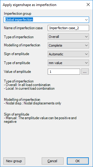
On the setting dialog the following parameters can be set:
-
Imperfection group: any eigenshape will belong to an imperfection group, which can be selected from the list. One imperfection group can contain more than one eigenshapes. If more than one eigenshapes are in an imperfection group, the effects of the eigenshapes will be added up during the application. With the New group button, a new group can be created.
-
Name of imperfection case: unique name can be added for the imperfection.
-
Type of imperfection:
- Overall: the imperfection case will be used for all of the load combinations
- Local: the imperfection will only be used in the load combination that caused the selected buckling shape used
-
Modelling of imperfection:
-
Complete: buckling mode will be applied on the model with all of the freedom (node displacement, rotation, warping)
-
Nodal disp.: only the nodal displacement will be applied as imperfection
-
-
Sign of amplitude:
-
Automatic: direction of the imperfection will be set properly for each of the load combinations; in case of normal way selection, for local imperfection type, only the manual option is available
-
Manual: direction of the imperfection will be accordingly to the sign of the given amplitude value
-
-
Type of amplitude:
-
mm value: maximum displacement value of the eigenshape can be given in mm. The other displacement values will be commensurable to the given amplitude.
-
multiplication factor: the calculated displacement values can be multiplied with this factor
-
-
Value of amplitude: value of the previously selected amplitude type has to be given
Pressing the OK button the eigenshape is applied as an imperfection with the set parameters.
Automatic amplitude calculation
Applying any imperfection, it is always a problem how to define the proper amplitude to have safe but economic results. The Eurocode EN 1993-1-1 gives some limited guidance for certain cases, based on these guidelines and self-developed procedures, Consteel can automatically determine the amplitude of imperfection using three different methods.
Click the three-dot icon () next to the Value of Amplitudefield in the dialog shown above. A new dialog box will appear where you can choose from the three possible amplitude calculation methods.
- Equivalent initial bow imperfection
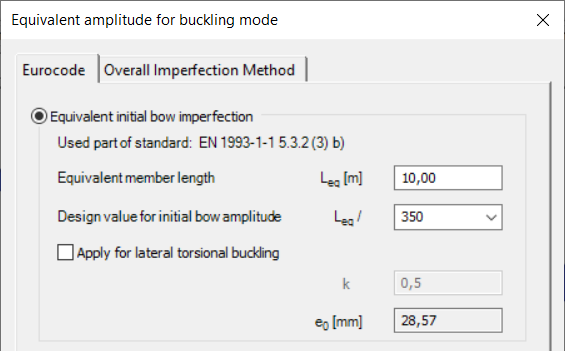
This option is based on table EN 1993-1-1 5.3.2 (3)b where initial bow amplitude ratios are defined depending on the corresponding buckling curve of the selected member. In order to evaluate the proper amplitude, the equivalent member length should also be specified (which is not necessarily equal to the system length of the selected member…) and the calculated value is displayed in mm. For the lateral-torsional buckling problem, an additional multiplication factor (k) can be defined for the amplitude. It is important to note that these values are officially valid only for simply supported straight, prismatic members with uniform compression (or bending), for other situations the user has to consider the special support, geometry, or loading effects when defining the initial bow. Finally, the calculated value (e0) is accepted by the OK button which automatically gets into the Value of amplitude input field.
- Equivalent imperfection based on the elastic critical buckling shape
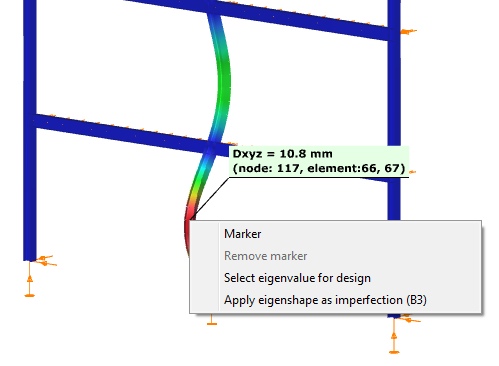
This option is based on the rules of EN 1993-1-1 5.3.2 (11). Since these rules are strongly connected to member parameters (cross-section type, shape, properties, buckling curve, etc.) the first task is the selection of a reference member which would be the suitable base for the amplitude calculations. This can be done by right click on the selected member and then choose the Apply eigenshape as imperfection where, as feedback, the name of the selected member is also appearing (e.g. B3). The selected member should be the dominant one in the certain buckling mode.
This method calculates fully automatically the amplitude value based on the selected axis of buckling with the following steps:
1. Calculation of the internal forces at the FE nodes of the member from the deformed shape equal to the selected buckling mode
2. Determination of the critical position where the relevant bending moment (My or Mz calculated in 1.) is the highest
3. Read the following information at the critical position:
i. Normal force value [NEd] from the first order analysis (without imperfection) – this value must be compression
ii. Relevant bending moment [My or Mz later displayed as MII denoted as EIhcr,max in the standard] I
iii. Cross section properties [class for compression, yield stress, area, relevant section modulus (Wy or Wz), relevant buckling curve]
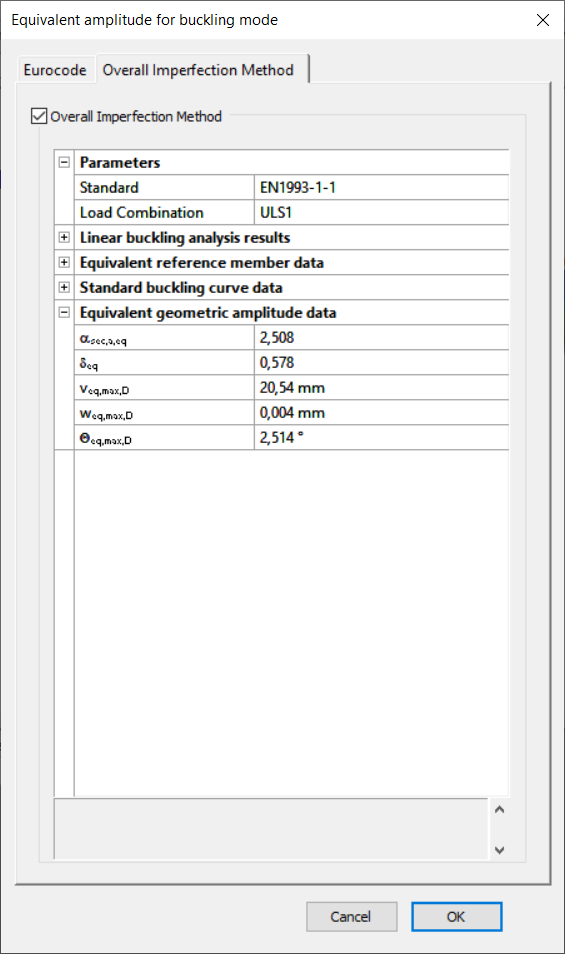
Finally the calculated value (hinit,max) is accepted by the OK button which automatically gets into the ‘Value of amplitude’ input field. This calculation is only applicable to buckling problems of a dominantly compressed member but with arbitrary support condition.
- Overall Imperfection Method (OIM)
Consteel's new, self-developed method for automatically determining the amplitude of imperfection, in full compliance with Eurocode regulations. A second-order analysis based imperfection scaled by this method and a cross-section design give the same utilization result as the conventional reduction factor method. This new method developed at Consteel is a fully generalized solution for the case of a simply-supported prismatic column loaded with centric concentrated force, which can be used for any non-uniformly or eccentrically loaded, arbitrarily supported member even with variable cross-section, and is fully compatible with EC. For example, for the above-mentioned simple case, the result is 100% equal to the result of the conventional reduction factor method.
Managing eigenshapes
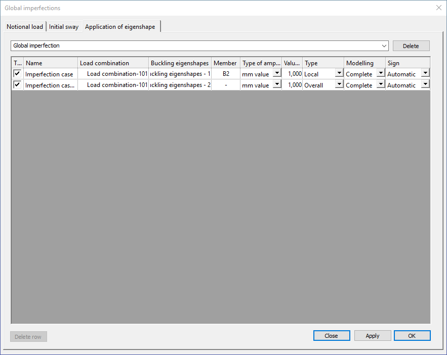
Previously created imperfection groups and imperfection cases (applied eigenshapes) can be managed on the Global Imperfections dialog’s Application of eigenshape tab.
By the first dropdown menu, imperfection groups can be switched, and whole imperfection group can be deleted with the Delete button.
In the middle part of the dialog can be seen the imperfection cases (applied eigenshapes) in the selected imperfection group. With the checkboxes in the first column each imperfection cases can be turn off and on. In the following columns, all of the previously setted parameters can checked and modified.
With the Delete row button the selected imperfection cases can be deleted from the imperfection group.
