CREATE
Creates an object.
Syntax
CREATE [Object ID] [Object type]
Object parameters...
Command parameters
| Command parameter | Assignment | Value format | Input options |
|---|---|---|---|
| Object ID | Required | String | Local, variable |
| Object type | Required | Predefined strings | Local, variable |
| Object parameters | Required | - | - |
Object ID:
A string of characters that is used to identify the object that is being created. The string can contain letters, numbers and special characters as well.
Object ID-s have to be unique for every object across all object types (eg.: sections, members, plates, loads, etc.).
Object type:
The type of object to be created.
Available object types:| Object type name | Object type |
|---|---|
| Structural members tab | - |
| Structural member | Structural_Member |
| Structural Plate | Structural_Plate |
| Haunch | Haunched_Member |
| Tapered member | Tapered_Member |
| Rectangular column reinforcement | RectangularColumnReinforcement |
| Circular column reinforcement | CircularColumnReinforcement |
| Steel material | Steel |
| Coated steel material | Coated_Steel |
| Concrete material | Concrete |
| Rebar material | Rebar |
| Point support | Support_Point |
| Line support | Support_Edge |
| Surface support | Support_Plate |
| Shear field | ShearField |
| Point support type | Support |
| Release type | Release |
| Link | Link |
| Smart link | SmartLink |
| Design parameters for concrete column | Design_Parameters_RCC |
| Loads tab | - |
| Load group | LoadGroup |
| Load case | LoadCase |
| Load combination | LoadCombination |
| Point load | NodeForce |
| Line load | MemberForce |
| Surface load (uniform) | PlateForce_Uniform |
| Surface load (linear) | PlateForce_Linear |
| Load transfer surface | LoadTransferSurface |
| Initial sway | InitialSway |
| Mass tab | - |
| Mass group | MassGroup |
| Mass case | MassCase |
| Mass combination | MassCombination |
| Point mass | NodeMass |
| Other | - |
| Portion | Portion |
Object parameters:
The available object parameters and their meaning depends on the chosen object type. Detailed description of all object parameters for each individual object type can be found below.
Detailed description of object types
Structural member
This command is analogous with the beam creation dialogue in Consteel:
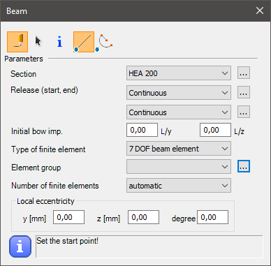
Syntax
CREATE [Object ID] Structural_Member [Section name]
[x1] [y1] [z1]
[x2] [y2] [z2]
Name [Object name]
ReleaseID_A [Release start]
ReleaseID_B [Release end]
EccType [Eccentricity reference]
Eccentricity_y [Eccentricity y]
Eccentricity_z [Eccentricity z]
Rotation [Rotation]
Geomimpv [Initial bow imperfection L/y]
Geomimpw [Initial bow imperfection L/z]
Fe_type [FE type]
Convergencetype [FE generation type]
Convergence [Number of FEs]
AverageEdgeLength_Web [FE size web]
AverageEdgeLength_flange [FE size flange]
Command parameters
| Command parameter | Assignment | Value format | Input options |
|---|---|---|---|
| Object ID | Required | String | Local, variable |
| Section name | Required | String | Local, variable |
| x1, y1, z1 | Required | Integer | Local, variable |
| x2, y2, z2 | Required | Integer | Local, variable |
| Object name | Optional | String | Local, variable |
| Release start | Optional | String | Local, variable |
| Release end | Optional | String | Local, variable |
| Eccentricity reference | Optional | Predefined strings | Local, variable |
| Eccentricity y | Optional | Numerical | Local, variable |
| Eccentricity z | Optional | Numerical | Local, variable |
| Rotation | Optional | Numerical | Local, variable |
| Initial bow imperfection L/y | Optional | Numerical | Local, variable |
| Initial bow imperfection L/z | Optional | Numerical | Local, variable |
| FE type | Optional | Predefined strings | Local, variable |
| FE generation type | Optional | Predefined strings | Local, variable |
| Number of FEs | Optional | Integer | Local, variable |
| FE size web | Optional | Numerical | Local, variable |
| FE size flange | Optional | Numerical | Local, variable |
Object ID:
A string of characters that is used to identify the object that is being created.
Section name:
Name of the section to be used for the member.
x1, y1, z1:
Coordinates of the starting point of the structural member.
x2, y2, z2:
Coordinates of the end point of the structural member.
Object name:
Name of the structural member.
Release start:
Release type at the starting point of the structural member. Any previously created release type name can be used.
Consteel has these release types already created by default:
- Continuous (default)
- w
- xx,yy,zz,w
- yy
- yy,zz
- yy,zz,w
- zz
Release end:
Release type at the end point of the structural member. Any previously created release type name can be used. The premade and default parameter inputs are the same as in case of the Release start parameter.
Eccentricity reference:
Available inputs:| Eccentricity reference name | Eccentricity reference |
|---|---|
| Reference line (0) | EccType_C |
| Bottom Left (1) | EccType_BL |
| Bottom Middle (2) | EccType_BM |
| Bottom Right (3) | EccType_BR |
| Middle Left (4) | EccType_ML |
| Middle Middle (5) | EccType_MM |
| Middle Right (6) | EccType_MR |
| Top Left (7) | EccType_TL |
| Top Middle (8) | EccType_TM |
| Top Right (9) | EccType_TR |
| Top of Web (10) | EccType_TWeb |
| Middle of Web (11) | EccType_MWeb |
| Bottom of Web (12) | EccType_BWeb |
Eccentricity y:
Structural member eccentricity in the local y direction.
Eccentricity z:
Structural member eccentricity in the local z direction.
Rotation:
Axial rotation of the structural member.
Initial bow imperfection L/y:
Initial bow imperfection of the member in the local y direction.
Initial bow imperfection L/z:
Initial bow imperfection of the member in the local z direction.
FE type:
Finite element type.
Available finite element types:| Finite element type name | Finite element type |
|---|---|
| 6 Degree Of Freedom beam | 6DOFelem |
| 7 Degree Of Freedom beam | 7DOFelem |
| Tension bar | TensionBar |
| Shell | Shell |
| Tension bar (X Brace) | XBrace |
FE generation type:
Finite element generation type.
Available inputs:- Automatic
- Manual
Number of FEs:
Number of finite elements. This parameter only applies if the FE type is "6DOFelem" or "7DOFelem".
FE size web:
Maximum edge size of shell element in the web. This parameter only applies if the FE type is "Shell".
FE size flange:
Maximum edge size of shell element in the web. This parameter only applies if the FE type is "Shell".
Sample code
Command only: (minimal parameters)
CREATE Mem_ID1 Structural_Member "HEA 200"
0 0 0
0 0 1000
With section creation and all parameters:
LOAD_SECTION_LIBRARY section "HEA 200"

CREATE Mem_ID1 Structural_Member "HEA 200"
0 0 0
0 0 1000
Name "Member 1"
ReleaseID_A Continuous
ReleaseID_B Continuous
EccType EccType_TM
Eccentricity_y 0
Eccentricity_z 0
Rotation 0
Geomimpv 0
Geomimpw 0
Fe_type 7dofelem
Convergencetype manual
Convergence 10
AverageEdgeLength_Web 10
AverageEdgeLength_flange 20
Structural plate
This command is analogous with the plate creation dialogue in Consteel, with the "draw polygon" option selected:
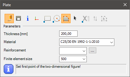
Syntax
CREATE [Object ID] Structural_Plate [Material name] [Plate thickness] [FE size] [Object name] [Group ID]
[x1] [y1] [z1]
[x2] [y2] [z2]
[x3] [y3] [z3]
etc.
Command parameters
| Command parameter | Assignment | Value format | Input options |
|---|---|---|---|
| Object ID | Required | String | Local, variable |
| Material name | Required | String | Local, variable |
| Plate thickness | Required | Numerical | Local, variable |
| FE size | Optional | Numerical | Local, variable |
| Object name | Optional | String | Local, variable |
| Group ID | Optional | String | Local, variable |
| x1, y1, z1 | Required | Integer | Local, variable |
| x2, y2, z2 | Required | Integer | Local, variable |
| x3, y3, z3 | Required | Integer | Local, variable |
Object ID:
A string of characters that is used to identify the object that is being created.
Material name:
Name of the material to be used.
Plate thickness:
Thickness of the plate in [mm].
FE size:
Maximum edge size of shell elements in [mm].
Object name:
Name of the structural plate.
Group ID:
ID of the element group.
x1, y1, z1:
Coordinates of 1. point of the structural plate.
x2, y2, z2:
Coordinates of 2. point of the structural plate.
x3, y3, z3:
Coordinates of 3. point of the structural plate. At least 3 points have to be defined for a plate creation. More point coordinates can be added into subsequent rows, for a polygon shape defined by more than 3 points.
Sample code
Minimal parameters and 3 points:
CREATE Plate_ID1 Structural_Plate "C25/30 EN 1992-1-1:2010" 200
0 0 0
3000 0 0
3000 3000 0
All parameters and 4 points:
CREATE Plate_ID1 Structural_Plate "C25/30 EN 1992-1-1:2010" 200 400
Name "Plate 1"
Group Group_ID1
0 0 0
3000 0 0
3000 3000 0
0 3000 0
Haunch
This command is analogous with the haunch creation dialogue in Consteel:
Hot rolled or welded haunch
Syntax
Hot rolled haunch:
CREATE [Object ID] Haunched_Member [Member ID] [Format] [L] [hs] [he] [Section name]
[x1] [y1] [z1]
[x2] [y2] [z2]
Welded haunch:
CREATE [Object ID] Haunched_Member [Member ID] [Format] [L] [hs] [he] [tw] [b] [tf]
[x1] [y1] [z1]
[x2] [y2] [z2]
Command parameters
| Command parameter | Assignment | Value format | Input options |
|---|---|---|---|
| Object ID | Required | String | Local, variable |
| Member ID | Required | String | Local, variable |
| Format | Required | Predefined strings | Local, variable |
| L | Required | Numerical | Local, variable |
| hs | Required | Numerical | Local, variable |
| he | Required | Numerical | Local, variable |
| Section name | Required | String | Local, variable |
| tw | Required | Numerical | Local, variable |
| b | Required | Numerical | Local, variable |
| tf | Required | Numerical | Local, variable |
| x1, y1, z1 | Required | Integer | Local, variable |
| x2, y2, z2 | Required | Integer | Local, variable |
Object ID:
A string of characters that is used to identify the object that is being created.
Member ID:
ID of the previously created structural member on which the haunch should be placed.
Format:
Alignment of the haunch.
Available input options:- Lower
- Symmetric
- Upper
L:
Length of the haunch.
hs:
Start height of the haunch.
he:
End height of the haunch.
Section name:
Name of the section to be used for the haunch. Only applicable if the haunch type is hot rolled.
tw:
Web thickness of the haunch. Only applicable if the haunch type is welded.
b:
Flange width of the haunch. Only applicable if the haunch type is welded.
tf:
Flange thickness of the haunch. Only applicable if the haunch type is welded.
x1, y1, z1:
Coordinates of the starting point of the haunch.
x2, y2, z2:
Coordinates for setting the direction of the haunch.
Sample code
Command only:
Hot rolled haunch:
CREATE Hau_ID1 Haunched_Member Mem_ID1 lower 2000 600 50 "IPE 300"
0 0 0
1 0 0
Welded haunch:
CREATE Hau_ID2 Haunched_Member Mem_ID2 lower 2000 600 50 6 150 10
0 2000 0
1 2000 0
With section and member creation:
Hot rolled haunch:
LOAD_SECTION_LIBRARY Sec_ID1 "IPE 300"

CREATE Mem_ID1 Structural_Member "IPE 300"
0 0 0
5000 0 0

CREATE Hau_ID1 Haunched_Member Mem_ID1 lower 2000 600 50 "IPE 300"
0 0 0
1 0 0
Welded haunch:
LOAD_SECTION_MACRO Sec_ID2 WLD-IH "WLD-IH (Descript)" "S 235 EN 10025-2" 150 10 300 8 150 10

CREATE Mem_ID2 Structural_Member "WLD-IH (Descript)"
0 2000 0
5000 2000 0

CREATE Hau_ID2 Haunched_Member Mem_ID2 lower 2000 600 50 6 150 10
0 2000 0
1 2000 0
Tapered member
This command is analogous with the tapered member creation dialogue in Consteel:
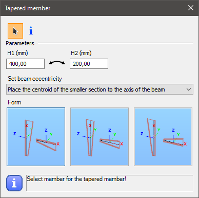
Syntax
CREATE [Object ID] Tapered_Member [Member ID] [Start height] [End height]
Format [Format]
ModEccentricity [Mod eccentricity]
Command parameters
| Command parameter | Assignment | Value format | Input options |
|---|---|---|---|
| Object ID | Required | String | Local, variable |
| Member ID | Required | String | Local, variable |
| Start height | Required | Numerical | Local, variable |
| End height | Required | Numerical | Local, variable |
| Format | Optional | Predefined strings | Local, variable |
Object ID:
A string of characters that is used to identify the object that is being created.
Member ID:
ID of the previously created structural member on which the tapering should be placed.
Starting height:
Starting height of the tapered member in [mm].
End height:
End height of the tapered member in [mm].
Format:
Alignment of the axis of the tapered member.
Available input options:- Bottom (default)
- Centric
- Top
Sample code
Command only: (minimal parameters)
CREATE Tapered_ID1 Tapered_Member MemID0 400 200
With added prerequisites (section and member definition) and all parameters:
LOAD_SECTION_MACRO Sec_ID1 WLD-IH Descript_Section "S 235 EN 10025-2" 100 10 200 6 100 10

CREATE Mem_ID1 Structural_Member Descript_Section
0 0 0
0 0 1000

CREATE Tapered_ID1 Tapered_Member Mem_ID1 400 200
Format Centric
Rectangular column reinforcement
This command is analogous with the rectangular column reinforcement creation dialogue in Consteel:
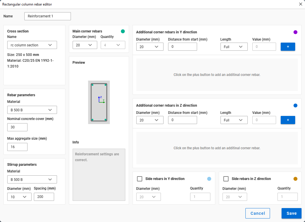
Syntax
CREATE [Object ID] RectangularColumnReinforcement [Section ID] [Main rebar diameter]
Name [Object name]
Command parameters
| Command parameter | Assignment | Value format | Input options |
|---|---|---|---|
| Object ID | Required | String | Local, variable |
| Section ID | Required | Section ID or name | Local, variable |
| Main rebar diameter | Required | Numerical | Local, variable |
| Object name | Optional | String | Local, variable |
Object ID:
A string of characters that is used to identify the object that is being created.
Section ID:
ID of the concrete section.
Main rebar diameter:
Diameter of the main rebar of the reinforcement in [mm].
Object name:
Name of the reinforcement.
Sample code
Command only: (minimal parameters)
CREATE ReinfColRect_ID1 RectangularColumnReinforcement Sec_ID1 22
With added prerequisites (section and member definition) and all parameters:
LOAD_SECTION_MACRO Sec_ID1 RC-ColRect "RC-ColRect (Descript)" "C25/30 EN 1992-1-1:2010" 255 567

CREATE ReinfColRect_ID1 RectangularColumnReinforcement Sec_ID1 22
Name "Reinforcement col rect 1"

CREATE Mem_ID1 Structural_Member "RC-ColRect (Descript)"
0 0 0
0 0 1000

SET Mem_ID1 ReinforcementID ReinfColRect_ID1
Circular column reinforcement
This command is analogous with the circular column reinforcement creation dialogue in Consteel:
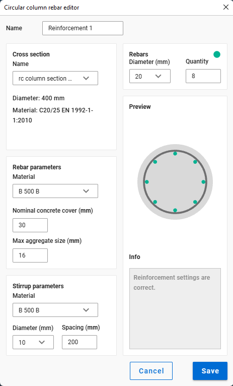
Syntax
CREATE [Object ID] CircularColumnReinforcement [Section ID] [Main rebar diameter]
Name [Object name]
Command parameters
| Command parameter | Assignment | Value format | Input options |
|---|---|---|---|
| Object ID | Required | String | Local, variable |
| Section ID | Required | Section ID or name | Local, variable |
| Main rebar diameter | Required | Numerical | Local, variable |
| Object name | Optional | String | Local, variable |
Object ID:
A string of characters that is used to identify the object that is being created.
Section ID:
ID of the concrete section.
Main rebar diameter:
Diameter of the main rebar of the reinforcement in [mm].
Object name:
Name of the reinforcement.
Sample code
Command only: (minimal parameters)
CREATE ReinfColCirc_ID1 CircularColumnReinforcement Sec_ID1 22
With added prerequisites (section and member definition) and all parameters:
LOAD_SECTION_MACRO Sec_ID1 RC-ColCirc "RC-ColCirc (Descript)" "C25/30 EN 1992-1-1:2010" 444

CREATE ReinfColCirc_ID1 CircularColumnReinforcement Sec_ID1 22
Name "Reinforcement col circ 1"

CREATE Mem_ID1 Structural_Member "RC-ColCirc (Descript)"
0 0 0
0 0 1000

SET Mem_ID1 ReinforcementID ReinfColCirc_ID1
Steel material
This command is analogous with the steel material creation dialogue in Consteel:
Syntax
CREATE [Object ID] Steel [Name] [ρ] [E] [ν] [α] [αfi] [fy1] [fy2] [fu1] [fu2] [ty] [tu]
Command parameters
| Command parameter | Parameter description | Assignment | Value format | Input options |
|---|---|---|---|---|
| Object ID | - | Required | String | Local, variable |
| Name | - | Required | String | Local, variable |
| ρ | Density | Required | Numerical | Local, variable |
| E | Elastic modulus | Required | Numerical | Local, variable |
| ν | Poisson factor | Required | Numerical | Local, variable |
| α | Thermal expansion coefficient | Required | Numerical | Local, variable |
| αfi | Thermal expansion coefficient in fire | Required | Numerical | Local, variable |
| fy1 | Yield strength 1 | Required | Numerical | Local, variable |
| fy2 | Yield strength 2 | Required | Numerical | Local, variable |
| fu1 | Ultimate strength 1 | Required | Numerical | Local, variable |
| fu2 | Ultimate strength 2 | Required | Numerical | Local, variable |
| ty | Thickness Y | Required | Numerical | Local, variable |
| tu | Thickness U | Required | Numerical | Local, variable |
Object ID:
A string of characters that is used to identify the object that is being created.
Name:
Name of the material.
Sample code
CREATE Steel_Mat_ID1 Steel "Custom steel name" 7850 210000 0.3 0.000012 0.000014 235 215 360 360 40 40
Coated steel material
This command is analogous with the coated steel material creation dialogue in Consteel:
Syntax
CREATE [Object ID] Coated_Steel [Name] [ρ] [E] [ν] [α] [αfi] [fyb] [fu] [tcoat]
Command parameters
| Command parameter | Parameter description | Assignment | Value format | Input options |
|---|---|---|---|---|
| Object ID | - | Required | String | Local, variable |
| Name | - | Required | String | Local, variable |
| ρ | Density | Required | Numerical | Local, variable |
| E | Elastic modulus | Required | Numerical | Local, variable |
| ν | Poisson factor | Required | Numerical | Local, variable |
| α | Thermal expansion coefficient | Required | Numerical | Local, variable |
| αfi | Thermal expansion coefficient in fire | Required | Numerical | Local, variable |
| fyb | Basic yield strength | Required | Numerical | Local, variable |
| fu | Ultimate strength | Required | Numerical | Local, variable |
| tcoat | Coating thickness | Required | Numerical | Local, variable |
Object ID:
A string of characters that is used to identify the object that is being created.
Name:
Name of the material.
Sample code
CREATE CSteel_Mat_ID1 Coated_Steel "Custom coated steel name" 7850 210000 0.3 0.000012 0.000014 350 420 0.02
Concrete material
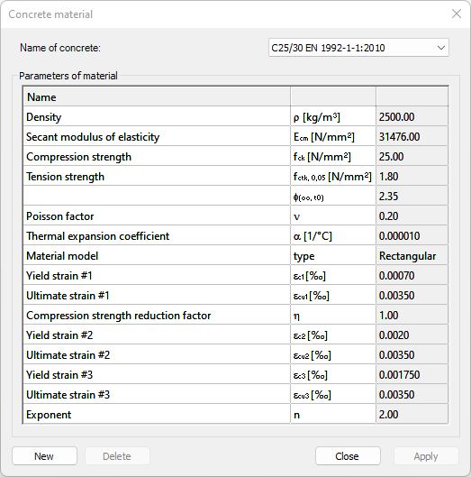
This command is analogous with the concrete material creation dialogue in Consteel:
Syntax
CREATE [Object ID] Concrete [Name] [ρ] [Ecm] [fck] [fctk,0,05] [fctm] [φ(∞,t0)] [ν] [α] [εc1] [εcu1] [η] [εc2] [εcu2] [εc3] [εcu3] [n]
Command parameters
| Command parameter | Parameter description | Assignment | Value format | Input options |
|---|---|---|---|---|
| Object ID | - | Required | String | Local, variable |
| Name | - | Required | String | Local, variable |
| ρ | Density | Required | Numerical | Local, variable |
| Ecm | Secant modulus of elasticity | Required | Numerical | Local, variable |
| fck | Compressive strength | Required | Numerical | Local, variable |
| fctk,0,05 | Characteristic tensile strength | |||
| fctm | Mean tensile strength | |||
| φ(∞,t0) | Final value of creep coefficient | |||
| ν | Poisson factor | Required | Numerical | Local, variable |
| α | Thermal expansion coefficient | Required | Numerical | Local, variable |
| Material model | - | Required | Numerical | Local, variable |
| εc1 | Yield strain #1 | Required | Numerical | Local, variable |
| εcu1 | Ultimite strain #1 | Required | Numerical | Local, variable |
| η | Compression strength reduction factor | Required | Numerical | Local, variable |
| εc2 | Yield strain #2 | Required | Numerical | Local, variable |
| εcu2 | Ultimite strain #2 | Required | Numerical | Local, variable |
| εc3 | Yield strain #3 | Required | Numerical | Local, variable |
| εcu3 | Ultimite strain #3 | Required | Numerical | Local, variable |
| n | Exponent | Required | Numerical | Local, variable |
Object ID:
A string of characters that is used to identify the object that is being created.
Name:
Name of the material.
Material model:
Available material models:
- DiagramRectangle
- DiagramBilinear
- DiagramParabolaRect
Sample code
CREATE Concrete_Mat_ID1 Concrete "Custom concrete name" 2500 31476 25 1.8 2.6 2.35 0.2 0.00001 DiagramRectangle 0.0007 0.0035 1 0.002 0.0035 0.00175 0.0035 2
Rebar material
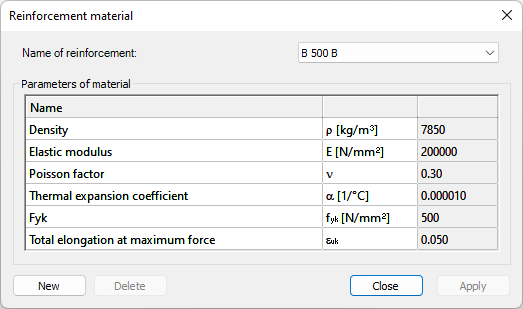
This command is analogous with the reinforcement material creation dialogue in Consteel:
Syntax
CREATE [Object ID] Rebar [Name] [ρ] [E] [ν] [α] [fyk] [εuk]
Command parameters
| Command parameter | Parameter description | Assignment | Value format | Input options |
|---|---|---|---|---|
| Object ID | - | Required | String | Local, variable |
| Name | - | Required | String | Local, variable |
| ρ | Density | Required | Numerical | Local, variable |
| E | Elastic modulus | Required | Numerical | Local, variable |
| ν | Poisson factor | Required | Numerical | Local, variable |
| α | Thermal expansion coefficient | Required | Numerical | Local, variable |
| fyk | Characteristic yield strength | Required | Numerical | Local, variable |
| εuk | Characteristic strain at maximum load | Required | Numerical | Local, variable |
Object ID:
A string of characters that is used to identify the object that is being created.
Name:
Name of the material.
Sample code
CREATE Rebar_Mat_ID1 Rebar "Custom rebar name" 7850 200000 0.3 0.00001 500 0.05
Point support
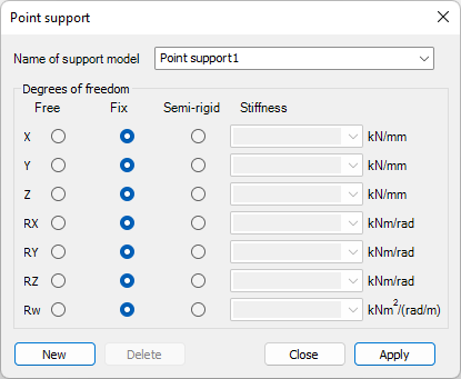
This command is analogous with the point support creation dialogue in Consteel:
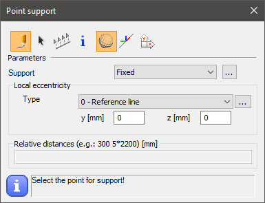
Syntax
CREATE [Object ID] Support_Point [Member ID] [Support type]
[x] [y] [z]
EccType [Eccentricity reference]
Command parameters
| Command parameter | Assignment | Value format | Input options |
|---|---|---|---|
| Object ID | Required | String | Local, variable |
| Member ID | Required | Member name or ID | Local, variable |
| Support type | Required | String | Local, variable |
| x, y, z | Required | Numerical | Local, variable |
| Eccentricity reference | Optional | Predefined strings | Local, variable |
Object ID:
A string of characters that is used to identify the object that is being created.
Member ID:
ID of the previously created structural member to which the support will be attached. The accepted input is either a member ID or the name of the member with this syntax: "NAME: [Member name]"
Support type:
The type of support. Any previously created support type name can be used.
Consteel has these support types already created by default:- Fixed
- x,y,z
- x,y,z,xx
- x,y,z,yy
- x,y,z,zz
- y,z,xx
- x,z,yy
- x,y,zz
- y,z
- x,z
- x,y
- x
- y
- z
- w
x, y, z:
Coordinates of the point support.
Eccentricity reference:
Available inputs:
| Eccentricity reference name | Eccentricity reference |
|---|---|
| Reference line (0) | EccType_C |
| Bottom Left (1) | EccType_BL |
| Bottom Middle (2) | EccType_BM |
| Bottom Right (3) | EccType_BR |
| Middle Left (4) | EccType_ML |
| Middle Middle (5) | EccType_MM |
| Middle Right (6) | EccType_MR |
| Top Left (7) | EccType_TL |
| Top Middle (8) | EccType_TM |
| Top Right (9) | EccType_TR |
Sample code
Command only: (minimal parameters)
CREATE PSup_ID1 Support_Point Member_ID1 x,y,z
0 0 0
With added prerequisites (section and member definition) and all parameters:
LOAD_SECTION_MACRO Sec_ID1 WLD-IH "Descript Section" "S 235 EN 10025-2" 100 10 200 6 100 10

CREATE Member_ID1 Structural_member "Descript Section"
0 0 0
0 0 3000

CREATE PSup_ID1 Support_Point Member_ID1 Fixed
0 0 0
EccType EccType_TM
Line support
This command is analogous with the line support creation dialogue in Consteel:
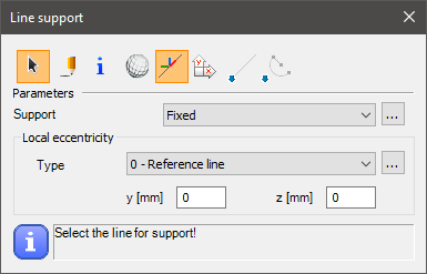
Syntax
CREATE [Object ID] Support_Edge [Member ID] [Support type]
Name [Object name]
CoordSys [Coordinate system]
EccType [Eccentricity reference]
Command parameters
| Command parameter | Assignment | Value format | Input options |
|---|---|---|---|
| Object ID | Required | String | Local, variable |
| Member ID | Required | Member name or ID | Local, variable |
| Support type | Required | String | Local, variable |
| Object name | Optional | String | Local, variable |
| Coordinate system | Optional | Predefined strings | Local, variable |
| Eccentricity reference | Optional | Predefined strings | Local, variable |
Object ID:
A string of characters that is used to identify the object that is being created.
Member ID:
ID of the previously created structural member to which the support will be attached. The accepted input is either a member ID or the name of the member with this syntax: "NAME: [Member name]"
Support type:
The type of support. Any previously created support type name can be used.
Consteel has these support types already created by default:
- Fixed
- Pinned
- y,xx
Object name:
Name of the line support.
Coordinate system:
With this parameter it can be specified which coordinate system to use for the load definition.
Available inputs:- Global (default)
- Local
Eccentricity reference:
Available inputs:| Eccentricity reference name | Eccentricity reference |
|---|---|
| Reference line (0) | EccType_C |
| Bottom Left (1) | EccType_BL |
| Bottom Middle (2) | EccType_BM |
| Bottom Right (3) | EccType_BR |
| Middle Left (4) | EccType_ML |
| Middle Middle (5) | EccType_MM |
| Middle Right (6) | EccType_MR |
| Top Left (7) | EccType_TL |
| Top Middle (8) | EccType_TM |
| Top Right (9) | EccType_TR |
Sample code
Command only: (minimal parameters)
CREATE LSup_ID1 Support_Edge Member_ID1 Fixed
With added prerequisites (section and member definition) and all parameters:
LOAD_SECTION_MACRO Sec_ID1 WLD-IH "WLD-IH (Descript)" "S 235 EN 10025-2" 100 10 200 6 100 10

CREATE Member_ID1 Structural_member "WLD-IH (Descript)"
0 0 0
0 0 3000

CREATE LSup_ID1 Support_Edge Member_ID1 Fixed
Name "Line support 1 (Descript)"
CoordSys Local
EccType EccType_TM
Surface support
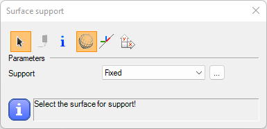
This command is analogous with the surface support creation dialogue in Consteel:
Syntax
CREATE [Object ID] Support_Plate [Plate ID] [Support type]
Name [Object name]
CoordSys [Coordinate system]
Command parameters
| Command parameter | Assignment | Value format | Input options |
|---|---|---|---|
| Object ID | Required | String | Local, variable |
| Plate ID | Required | Plate name or ID | Local, variable |
| Support type | Required | String | Local, variable |
| Object name | Optional | String | Local, variable |
| Coordinate system | Optional | Predefined strings | Local, variable |
Object ID:
A string of characters that is used to identify the object that is being created.
Plate ID:
ID of the previously created structural plate to which the support will be attached. The accepted input is either a plate ID or the name of the plate with this syntax: "NAME: [Plate name]"
Support type:
The type of support. Any previously created surface support type name can be used.
Object name:
Name of the surface support.
Coordinate system:
With this parameter it can be specified which coordinate system to use for the load definition.
Available inputs:- Global (default)
- Local
Sample code
Command only: (minimal parameters)
CREATE SurfSup_ID1 Support_Plate Plate_ID1 Fixed
With added prerequisites (plate creation) and all parameters:
CREATE Plate_ID1 Structural_Plate "C25/30 EN 1992-1-1:2010" 200
0 0 0
3000 0 0
3000 3000 0

CREATE SurfSup_ID1 Support_Plate Plate_ID1 Fixed
Name "Surface support 1"
CoordSys Local
Shear field
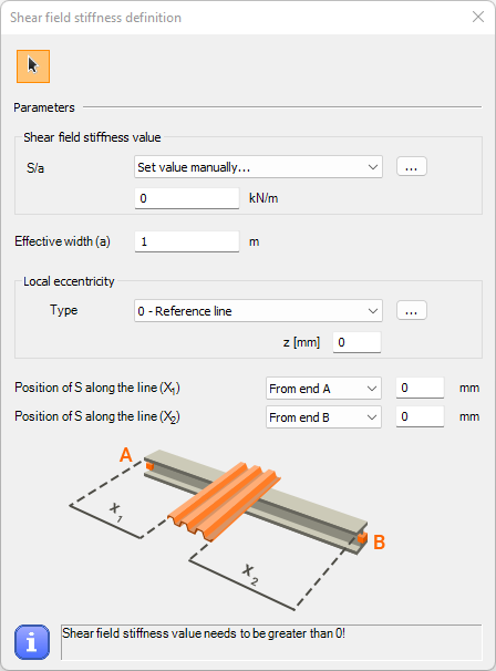
This command is analogous with the shear field creation dialogue in Consteel:
Syntax
CREATE [Object ID] ShearField [Member ID] [Stiffness definition type] [Stiffness] [Effective width] [Eccentricity z]
[Reference point 1] [Reference point 2]
[Distance 1] [Distance 2]
EccType [Eccentricity reference]
Command parameters
| Command parameter | Assignment | Value format | Input options |
|---|---|---|---|
| Object ID | Required | String | Local, variable |
| Member ID | Required | Member name or ID | Local, variable |
| Stiffness definition type | Required | Predefined strings | Local, variable |
| Stiffness | Required | Numerical | Local, variable |
| Effective width | Required | Numerical | Local, variable |
| Eccentricity z | Optional | Numerical | Local, variable |
| Reference point 1 | Required | Numerical | Local, variable |
| Reference point 2 | Required | Numerical | Local, variable |
| Distance 1 | Required | Numerical | Local, variable |
| Distance 2 | Required | Numerical | Local, variable |
| Eccentricity reference | Optional | Predefined strings | Local, variable |
Object ID:
A string of characters that is used to identify the object that is being created.
Member ID:
ID of the member to which the shear field will be attached. The accepted input is either a member ID or the name of the member with this syntax: "NAME: [Member name]"
Stiffness definition type:
Available inputs:- Manual
Stiffness:
Stiffness value of the shear field in [kN/m]. Must be a positive number.
Effective width:
Effective width of the sehar field in [m]. Must be a non-negative number.
Eccentricity z:
Shear field eccentricity in the local z direction.
Reference point 1:
Parameter that controls the starting location of the shear field.
Available inputs:
- 0 → from end A
- 1 → from end B
Reference point 2:
Parameter that controls the end location of the shear field.
Available inputs:
- 0 → from end A
- 1 → from end B
- 2 → Relative
Distance 1:
Distance of the start of the shear field from the member end set by the Reference point 1 parameter.
Distance 2:
Distance of the end of the shear field from the member end set by the Reference point 2 parameter. If Reference point 2 = 2 (Relative), then the length of the shear field is measured from the starting point.
Eccentricity reference:
Available inputs:| Eccentricity reference name | Eccentricity reference |
|---|---|
| Reference line (0) | EccType_C |
| Bottom Middle (2) | EccType_BM |
| Middle Middle (5) | EccType_MM |
| Top Middle (8) | EccType_TM |
Sample code
Command only: (minimal parameters)
CREATE SF_ID1 ShearField Member_ID1 Manual 1000 5
0 1
0 0
With section, member creation and all parameters:
LOAD_SECTION_MACRO SecID WLD-IH "I 200 Welded" "S 235 EN 10025-2" 100 10 200 6 100 10

CREATE Member_ID1 Structural_member "I 200 Welded"
0 0 0
6000 0 0

CREATE SF_ID1 ShearField Member_ID1 Manual 1000 5 10
0 1
200 400
EccType EccType_TM
Point support type
This command is analogous with the point support type creation dialogue in Consteel:
Syntax
CREATE [Object ID] Support [Name] [x] [y] [z] [xx] [yy] [zz] [w]
Command parameters
| Command parameter | Assignment | Value format | Input options |
|---|---|---|---|
| Object ID | Required | String | Local, variable |
| Name | Required | String | Local, variable |
| x, y, z, xx, yy, zz, w | Required | Predefined strings or numerical | Local, variable |
Object ID:
A string of characters that is used to identify the object that is being created.
Name:
Name of the object that will be created.
Degree of freedom (DOF) parameters: x, y, z, xx, yy, zz, w
| DOF parameter | Parameter description | Stiffness dimension |
|---|---|---|
| x | Translational degree of freedom in x direction | kN/mm |
| y | Translational degree of freedom in y direction | kN/mm |
| z | Translational degree of freedom in z direction | kN/mm |
| xx | Rotational degree of freedom around x axis | kNm/rad |
| yy | Rotational degree of freedom around y axis | kNm/rad |
| zz | Rotational degree of freedom around z axis | kNm/rad |
| w | Warping | kNm2/(rad/m) |
All DOF parameters work similarly. Each DOF can be fixed, free, or semi-rigid.
Available inputs:- Fix
- Free
- Numerical input (eg. 1.234)
If a numerical input is given then the corresponding DOF will be semi-rigid, and the given number will become the stiffness of that DOF. The dimension of the stiffness depends on which DOF it is applied to. The actual stiffness dimensions can be seen in the table above for every different DOF.
Sample code
CREATE PSup_Type_ID1 Support "Custom support type name" Fix Free 1.234 Fix Fix Fix Fix
Release type
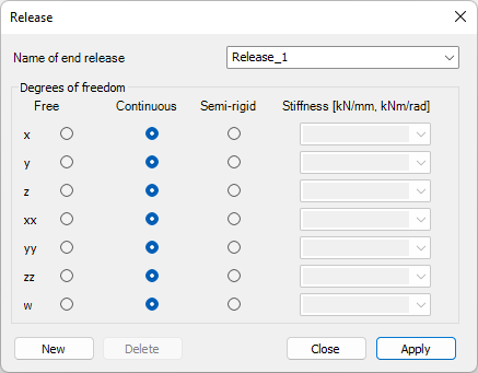
This command is analogous with the release type creation dialogue in Consteel:
Syntax
CREATE [Object ID] Release [Name] [x] [y] [z] [xx] [yy] [zz] [w]
Command parameters
| Command parameter | Assignment | Value format | Input options |
|---|---|---|---|
| Object ID | Required | String | Local, variable |
| Name | Required | String | Local, variable |
| x, y, z, xx, yy, zz, w | Required | Predefined strings or numerical | Local, variable |
Object ID:
A string of characters that is used to identify the object that is being created.
Name:
Name of the object that will be created.
Degree of freedom (DOF) parameters: x, y, z, xx, yy, zz, w
| DOF parameter | Parameter description | Stiffness dimension |
|---|---|---|
| x | Translational degree of freedom in x direction | kN/mm |
| y | Translational degree of freedom in y direction | kN/mm |
| z | Translational degree of freedom in z direction | kN/mm |
| xx | Rotational degree of freedom around x axis | kNm/rad |
| yy | Rotational degree of freedom around y axis | kNm/rad |
| zz | Rotational degree of freedom around z axis | kNm/rad |
| w | Warping | kNm2/(rad/m) |
All DOF parameters work similarly. Each DOF can be fixed, free, or semi-rigid.
Available inputs:- Fix
- Free
- Numerical input (eg. 1.234)
If a numerical input is given then the corresponding DOF will be semi-rigid, and the given number will become the stiffness of that DOF. The dimension of the stiffness depends on which DOF it is applied to. The actual stiffness dimensions can be seen in the table above for every different DOF.
Sample code
CREATE Release_Type_ID1 Release "Custom release type name" Fix Free 1.234 Fix Fix Fix Fix
Link
This command is analogous with the link element creation dialogue in Consteel:
Syntax
CREATE [Object ID] Link
[x1] [y1] [z1]
[x2] [y2] [z2]
Rotation [Rotation]
InterfacePos [Interface position]
ReleaseID [Release]
FromObjectID [From object ID]
ToObjectID [To object ID]
Command parameters
| Command parameter | Assignment | Value format | Input options |
|---|---|---|---|
| Object ID | Required | String | Local, variable |
| x1, y1, z1 | Required | Numerical | Local, variable |
| x2, y2, z2 | Required | Numerical | Local, variable |
| Rotation | Optional | Numerical | Local, variable |
| Interface position | Optional | Numerical | Local, variable |
| Release | Optional | String | Local, variable |
| From object ID | Optional | Object ID | Local, variable |
| To object ID | Optional | Object ID | Local, variable |
Object ID:
A string of characters that is used to identify the object that is being created.
x1, y1, z1:
Coordinates of 1. point of the link.
x2, y2, z2:
Coordinates of 2. point of the link.
Rotation:
Axial rotation of the local coordinate system of the link in degrees. Default: 0.
Interface position:
The position of the interface, or release along the length of the link. Acceptable inputs are decimal fraction numbers from 0 to 1. Default: 0.
Release:
The type of release at the interface position. Any previously created release type name can be used.
Consteel has these release types already created by default:
- Continuous (default)
- w
- xx,yy,zz,w
- yy
- yy,zz
- yy,zz,w
- zz
From object ID:
The ID of an object that the start point of the link is connecting to. This parameter accepts an ID of the following object types: structural member, structural plate.
To object ID:
The ID of an object that the end point of the link is connecting to. This parameter accepts an ID of the following object types: structural member, structural plate.
Sample code
Command only: (minimal parameters)
Create Link_ID1 Link
1000 0 0
1000 0 600
With added prerequisites (section and member definition) and all parameters:
LOAD_SECTION_MACRO Sec_ID1 WLD-IH "Descript Section" "S 235 EN 10025-2" 100 10 200 6 100 10

CREATE Member_ID1 Structural_member "Descript Section"
1000 0 0
5000 0 0

CREATE Member_ID2 Structural_member "Descript Section"
1000 0 600
5000 0 600

CREATE Link_ID1 Link
1000 0 0
1000 0 600
Rotation 20
InterfacePos 0.5
ReleaseID yy
FromObjectID Member_ID1
ToObjectID Member_ID2
Smart link
This command is analogous with the smart link creation dialogue in Consteel:
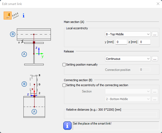
Syntax
CREATE [Object ID] SmartLink [Member ID]
[x] [y] [z]
MainBeamEccType [Main beam eccentricity type]
MainBeamEccY [Main beam eccentricity y]
MainBeamEccZ [Main beam eccentricity z]
ReleaseID [Release]
InterfacePos_CalcType [Interface position calculation type]
InterfacePos [Interface position]
IsSubBeam [Is Subbeam]
SubBeamSectionID [SubBeam section ID]
SubBeamEccType [SubBeam eccentricity type]
Command parameters
| Command parameter | Assignment | Value format | Input options |
|---|---|---|---|
| Object ID | Required | String | Local, variable |
| Member ID | Required | String | Local, variable |
| x, y, z | Required | Numerical | Local, variable |
| Main beam eccentricity type | Optional | Predefined strings | Local, variable |
| Main beam eccentricity y | Optional | Numerical | Local, variable |
| Main beam eccentricity z | Optional | Numerical | Local, variable |
| Release ID | Optional | Release name or ID | Local, variable |
| Interface position calculation type | Optional | Predefined strings | Local, variable |
| Interface position | Optional | Numerical | Local, variable |
| Is Subbeam | Optional | Predefined strings | Local, variable |
| SubBeam section ID | Optional | Section name or ID | Local, variable |
| SubBeam eccentricity type | Optional | Predefined strings | Local, variable |
Object ID:
A string of characters that is used to identify the object that is being created.
Member ID:
A string of characters that is used to identify the structural member that the smart link connects to. This member will have the "Main section (A)".
x, y, z:
Coordinates of the insertion point of the smart link.
Main beam eccentricity type:
Eccentricity reference for the main beam.
Available inputs:| Eccentricity reference name | Eccentricity reference |
|---|---|
| Reference line (0) | EccType_C |
| Bottom Left (1) | EccType_BL |
| Bottom Middle (2) | EccType_BM |
| Bottom Right (3) | EccType_BR |
| Middle Left (4) | EccType_ML |
| Middle Middle (5) | EccType_MM |
| Middle Right (6) | EccType_MR |
| Top Left (7) | EccType_TL |
| Top Middle (8) | EccType_TM |
| Top Right (9) | EccType_TR |
| Top of Web (10) | EccType_TWeb |
| Middle of Web (11) | EccType_MWeb |
| Bottom of Web (12) | EccType_BWeb |
Main beam eccentricity y:
Connection eccentricity to the main section in the local y direction.
Main beam eccentricity z:
Connection eccentricity to the main section in the local z direction.
Release ID:
The type of release at the interface position. Any previously created release type name can be used. If release type name is used, then it should be prefixed with "NAME: ".
Consteel has these release types already created by default:
- Continuous (default)
- w
- xx,yy,zz,w
- yy
- yy,zz
- yy,zz,w
- zz
Interface position calculation type:
Calculation type of the interface position.
Available inputs:- Automatic
- Manual
Interface position:
The position of the interface, or release along the length of the smart link. Acceptable inputs are decimal fraction numbers from 0 to 1. Default: 0.
Is Subbeam:
Setting that switches on or off the eccentricity options for the connecting section.
Available inputs:- 1 / Yes
- 0 / No
Subbeam section ID:
ID of the connecting section. The name or ID of any previously loaded section might be used. If section name is used, then it should be prefixed with "NAME: ".
Subbeam eccentricity type:
Eccentricity reference for the connecting section.
Available inputs:| Eccentricity reference name | Eccentricity reference |
|---|---|
| Reference line (0) | EccType_C |
| Bottom Middle (2) | EccType_BM |
| Middle Middle (5) | EccType_MM |
| Top Middle (8) | EccType_TM |
Sample code
Command only: (minimal parameters)
CREATE SmartLinkID SmartLink Mem_ID1
2500 0 0
With added prerequisites (section and member definition) and all parameters:
LOAD_SECTION_LIBRARY Sec_ID1 "IPE 200"

LOAD_SECTION_LIBRARY Sec_ID2 "IPE 100"

CREATE Release_Type_ID1 Release "Custom release type name" Fix Free 1.234 Fix Fix Fix Fix

CREATE Mem_ID1 Structural_member "IPE 200"
0 0 0
5000 0 0

CREATE SmartLinkID SmartLink Mem_ID1
2500 0 0
MainBeamEccType EccType_TM
MainBeamEccY 10
MainBeamEccZ 20
ReleaseID Release_Type_ID1
InterfacePos_CalcType Manual
InterfacePos 0.7
IsSubBeam Yes
SubBeamSectionID Sec_ID2
SubBeamEccType EccType_BM
Design parameters for concrete column
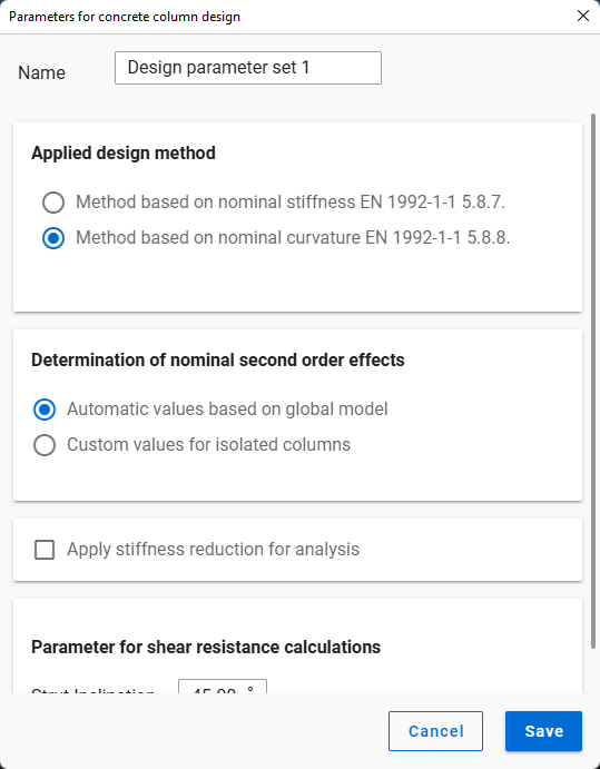
This command is analogous with the concrete column design parameters object creation dialogue in Consteel:
Syntax
CREATE [Object ID] Design_Parameters_RCC
Name [Object name]
Command parameters
| Command parameter | Assignment | Value format | Input options |
|---|---|---|---|
| Object ID | Required | String | Local, variable |
| Object name | Optional | String | Local, variable |
Object ID:
A string of characters that is used to identify the object that is being created.
Object name:
Name of the design parameters object.
Sample code
Command only: (minimal parameters)
CREATE DesParam_ID1 Design_Parameters_RCC
With added prerequisites (section and member definition) and all parameters:
LOAD_SECTION_MACRO Sec_ID1 RC-ColRect "RC-ColRect (Descript)" "C25/30 EN 1992-1-1:2010" 255 567

CREATE Mem_ID1 Structural_Member "RC-ColRect (Descript)"
0 0 0
0 0 1000

CREATE DesParam_ID1 Design_Parameters_RCC
Name "Design param 1"

SET Mem_ID1 DesignParamID DesParam_ID1
Load group
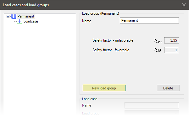
This command is analogous with the load group creation button in Consteel:
Syntax
CREATE [Object ID] LoadGroup
Name [Object name]
LoadGroupType [Load group type]
Factor_0 [Factor 0]
Factor_1 [Factor 1]
Factor_2 [Factor 2]
Factor_3 [Factor 3]
Command parameters
| Command parameter | Assignment | Value format | Input options |
|---|---|---|---|
| Object ID | Required | String | Local, variable |
| Object name | Required | String | Local, variable |
| Load group type | Required | Predefined strings | Local, variable |
| Factors 0-3 | Optional | Numerical | Local, variable |
Object ID:
A string of characters that is used to identify the object that is being created.
Object name:
Name of the load group.
Load group type:
Type of the load group.
Available load group types:| Load group type name | Load group type |
|---|---|
| EN standard | - |
| EN, Permanent | LGType_EN_P |
| EN, Variable (Transient) | LGType_EN_T |
| EN, Meteorological | LGType_EN_M |
| EN, Wind | LGType_EN_W |
| EN, Snow | LGType_EN_S |
| EN, Crane | LGType_EN_C |
| EN, Accidental | LGType_EN_A |
| EN, Accidental snow | LGType_EN_AS |
| EN, Seismic (Earthquake) | LGType_EN_E |
| AISC standard | - |
| AISC, Dead load | LGType_AISC_D |
| AISC, Fluid load | LGType_AISC_F |
| AISC, Live load | LGType_AISC_L |
| AISC, Roof live load | LGType_AISC_Lr |
| AISC, Rain load | LGType_AISC_R |
| AISC, Snow load | LGType_AISC_S |
| AISC, Weight of ice | LGType_AISC_DI |
| AISC, Wind load | LGType_AISC_W |
| AISC, Wind on ice | LGType_AISC_Wi |
| AISC,Wind load for SLS | LGType_AISC_Wa |
| AISC, Flood load | LGType_AISC_Fa |
| AISC, Load from extraordinary event | LGType_AISC_Ak |
Factors 0-3:
Safety and combination factors attached to the load group.
- Factor 0: safety factor (γG or γQ)
- Factor 1: combination factor (Ψ0)
- Factor 2: factor for frequent load level (Ψ1)
- Factor 3: factor for quasi permanent load level (Ψ2)
Sample code
EN Permanent load group: (minimal parameters)
CREATE LG_ID1 LoadGroup
Name "Permanent (Descript)"
LoadGroupType LGType_EN_P
EN Variable load group: (all parameters)
CREATE LG_ID1 LoadGroup
Name "Variable (Descript)"
LoadGroupType LGType_EN_T
Factor_0 1.35
Factor_1 1
Factor_2 0.9
Factor_3 0
Load case
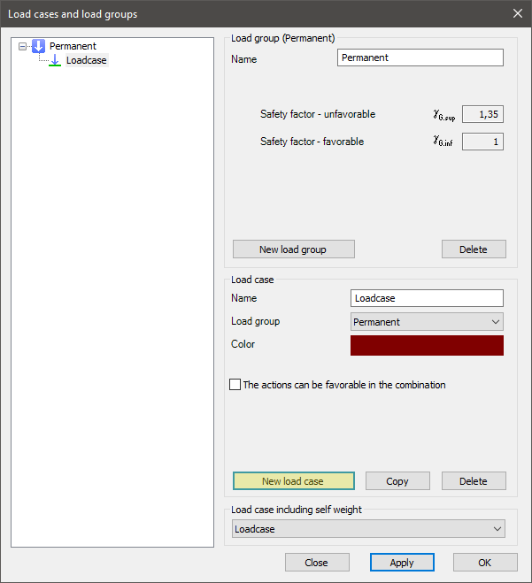
This command is analogous with the load case creation button in Consteel:
Syntax
CREATE [Object ID] LoadCase
Name [Object name]
LoadGroupID [Load group ID]
CanBeFavourable [Can be favourable]
NotMainInTransientCmb [Not main in variable combination]
NotMainInAccidentalCmb [Not main in accidental combination]
Command parameters
| Command parameter | Assignment | Value format | Input options |
|---|---|---|---|
| Object ID | Required | String | Local, variable |
| Object name | Optional | String | Local, variable |
| Load group ID | Optional | String | Local, variable |
| Can be favourable | Optional | Boolean | Local, variable |
| Not main in variable combination | Optional | Boolean | Local, variable |
| Not main in accidental combination | Optional | Boolean | Local, variable |
Object ID:
A string of characters that is used to identify the object that is being created.
Object name:
Name of the load case. If not specified, the default name is: LoadCase.
Load group ID:
ID of the load group that will contain the created load case. If not specified, then the load case will be created within the default permanent load group.
Can be favourable:
Boolean parameter that controls if the load case can be favourable in a combination or not. Accepted inputs: "0" or "1". If not specified the default value is "1".
- 0 → turned off, load can not be favorable
- 1 → turned on, load can be favorable
Not main in variable combination:
Boolean parameter that controls if the load case can be main in permanent and variable combinations or not. Accepted inputs: "0" or "1". If not specified the default value is "0".
- 0 → turned off, load can not be main
- 1 → turned on, load can be main
Not main in accidental combination:
Boolean parameter that controls if the load case can be main in accidental combinations or not. Accepted inputs: "0" or "1". If not specified the default value is "0".
- 0 → turned off, load can not be main
- 1 → turned on, load can be main
Sample code
Command only: (minimal parameters)
CREATE LCaseID01 LoadCase
With load group creation and all parameters:
CREATE LG_ID1 LoadGroup
Name "Permanent (Descript)"
LoadGroupType LGType_EN_P

CREATE LCase_ID1 LoadCase
Name "Load case 1 (Descript)"
LoadGroupID LG_ID1
CanBeFavourable 0
NotMainInTransientCmb 0
NotMainInAccidentalCmb 0
Load combination
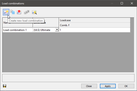
This command is analogous with the load combination creation button in Consteel:
Syntax
CREATE [Object ID] LoadCombination
Name [Object name]
Type [Combination type]
[Load case ID 1] [Load case combination factor 1]
[Load case ID 2] [Load case combination factor 2]
etc.
Command parameters
| Command parameter | Assignment | Value format | Input options |
|---|---|---|---|
| Object ID | Required | String | Local, variable |
| Object name | Optional | String | Local, variable |
| Combination type | Optional | Predefined strings | Local, variable |
| Load case IDs | Optional | Load case name or ID | Local, variable |
| Load case combination factors | Optional | Numerical | Local, variable |
Object ID:
A string of characters that is used to identify the object that is being created.
Object name:
Name of the load combination. If not specified, the default name is: Load combination1.
Combination type:
Type of the combination.
Available combination types:- ULS_STR_PersistentOrTransient
- ULS_GEO_PersistentOrTransient
- ULS_EQU_PersistentOrTransient
- ULS_Accidental
- ULS_Seismic
- ULS_Other (default)
- SLS_Characteristic_GQ
- SLS_Frequent_GQ
- SLS_QuasiPermanent_GQ
- SLS_Characteristic_Q
- SLS_Frequent_Q
- SLS_QuasiPermanent_Q
- SLS_Seismic
- SLS_Other
Load case IDs:
ID of load cases for which combination factors will be specified. The accepted input is either a load case ID or the name of a load case with this syntax: "NAME: [Load case name]"
Load case combination factors:
Combination factors assigned to load cases in the same row.
Sample code
Command only: (minimal parameters)
CREATE LComb_ID1 LoadCombination
"NAME: Loadcase" 1
With getting load case ID and all parameters:
FILTER LCase_IDs
Objecttypes Loadcase

ARRAY_GET LCase_IDs 0 LCase_ID1

CREATE LComb_ID1 LoadCombination
Name "Load combination (Descript)"
Type ULS_STR_PersistentOrTransient
$LCase_ID1 1
Point load
This command is analogous with the point load creation dialogue in Consteel:
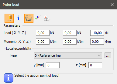
Syntax
CREATE [Object ID] NodeForce [Load case ID] [Member ID] [Coordinate system]
[x] [y] [z]
[Fx] [Fy] [Fz]
[Mx] [My] [Mz]
EccType [Eccentricity reference]
Command parameters
| Command parameter | Assignment | Value format | Input options |
|---|---|---|---|
| Object ID | Required | String | Local, variable |
| Load case ID | Required | Load case name or ID | Local, variable |
| Member ID | Required | Member name or ID | Local, variable |
| Coordinate system | Optional | Predefined string | Local, variable |
| x, y, z | Required | Numerical | Local, variable |
| Fx, Fy, Fz | Required | Numerical | Local, variable |
| Mx, My, Mz | Required | Numerical | Local, variable |
| Eccentricity reference | Optional | Predefined strings | Local, variable |
Object ID:
A string of characters that is used to identify the object that is being created.
Load case ID:
ID of the load case that will contain the load. The accepted input is either a load case ID or the name of a load case with this syntax: "NAME: [Load case name]"
Member ID:
ID of the member to which the load will be attached. The accepted input is either a member ID or the name of the member with this syntax: "NAME: [Member name]"
Coordinate system:
With this parameter it can be specified which coordinate system to use for the load definition. If unspecified the default is the global coordinate system. If specified, the only accepted input is: "local".
x, y, z:
Coordinates of the application point of the load.
Alternatively the location of the point load can be defined relatively along the length of the member it is attached to. For this definition use the following syntax replacing the x, y, z coordinates: "Rel ", where the Relative position parameter can be any number between 0 and 1. For example:
CREATE PLoad_ID1 NodeForce "NAME: Loadcase" Mem_ID1
Rel 0.6
0 100 -100
0 0 0
Fx, Fy, Fz:
Force components of the point load.
Mx, My, Mz:
Moment components of the point load.
Eccentricity reference:
Available inputs:| Eccentricity reference name | Eccentricity reference |
|---|---|
| Reference line (0) | EccType_C |
| Bottom Left (1) | EccType_BL |
| Bottom Middle (2) | EccType_BM |
| Bottom Right (3) | EccType_BR |
| Middle Left (4) | EccType_ML |
| Middle Middle (5) | EccType_MM |
| Middle Right (6) | EccType_MR |
| Top Left (7) | EccType_TL |
| Top Middle (8) | EccType_TM |
| Top Right (9) | EccType_TR |
Sample code
Command only: (minimal parameters)
CREATE PLoad_ID1 NodeForce "NAME: Loadcase" Mem_ID1
0 0 3000
0 100 -100
0 0 0
With section, load group, load case, member creation and all parameters:
Note that in this example the load is given in the member's local coordinate system.
LOAD_SECTION_LIBRARY Sec_ID1 "HEA 200"

CREATE LG_ID1 LoadGroup
Name "Permanent (Descript)"
LoadGroupType LGType_EN_P

CREATE LCase_ID1 LoadCase
Name "Load case 1 (Descript)"
LoadGroupID LG_ID1

CREATE Mem_ID1 Structural_member "HEA 200"
0 0 0
0 0 3000

CREATE PLoad_ID1 NodeForce LCase_ID1 Mem_ID1 local
0 0 3000
-100 0 0
0 0 0
EccType EccType_TM
Line load
This command is analogous with the line load creation dialogue in Consteel:
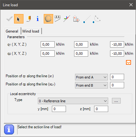
Syntax
CREATE [Object ID] MemberForce [Load case ID] [Member ID] [Coordinate system]
[Reference point 1] [Reference point 2]
[Distance 1] [Distance 2]
[Fx1] [Fy1] [Fz1]
[Fx2] [Fy2] [Fz2]
EccType [Eccentricity reference]
Command parameters
| Command parameter | Assignment | Value format | Input options |
|---|---|---|---|
| Object ID | Required | String | Local, variable |
| Load case ID | Required | Load case name or ID | Local, variable |
| Member ID | Required | Member name or ID | Local, variable |
| Coordinate system | Optional | Predefined string | Local, variable |
| Reference point 1 | Required | Numerical | Local, variable |
| Reference point 2 | Required | Numerical | Local, variable |
| Distance 1 | Required | Numerical | Local, variable |
| Distance 2 | Required | Numerical | Local, variable |
| Fx1, Fy1, Fz1 | Required | Numerical | Local, variable |
| Fx2, Fy2, Fz2 | Required | Numerical | Local, variable |
| Eccentricity reference | Optional | Predefined strings | Local, variable |
Object ID:
A string of characters that is used to identify the object that is being created.
Load case ID:
ID of the load case that will contain the load. The accepted input is either a load case ID or the name of a load case with this syntax: "NAME: [Load case name]"
Member ID:
ID of the member to which the load will be attached. The accepted input is either a member ID or the name of the member with this syntax: "NAME: [Member name]"
Coordinate system:
With this parameter it can be specified which coordinate system to use for the load definition. If unspecified the default is the global coordinate system. If specified, the only accepted input is: "local".
Reference point 1:
Parameter that controls the starting location of the line load.
Available inputs:
- 0 → from end A
- 1 → from end B
Reference point 2:
Parameter that controls the end location of the line load.
Available inputs:
- 0 → from end A
- 1 → from end B
- 2 → Relative
Distance 1:
Distance of the start of the line load from the member end set by the Reference point 1 parameter.
Distance 2:
Distance of the end of the line load from the member end set by the Reference point 2 parameter. If Reference point 2 = 2 (Relative), then the length of the line load is measured from the starting point.
Fx1, Fy1, Fz1:
Force components at the starting point of the line load.
Fx2, Fy2, Fz2:
Force components at the end point of the line load.
Eccentricity reference:
Available inputs:| Eccentricity reference name | Eccentricity reference |
|---|---|
| Reference line (0) | EccType_C |
| Bottom Left (1) | EccType_BL |
| Bottom Middle (2) | EccType_BM |
| Bottom Right (3) | EccType_BR |
| Middle Left (4) | EccType_ML |
| Middle Middle (5) | EccType_MM |
| Middle Right (6) | EccType_MR |
| Top Left (7) | EccType_TL |
| Top Middle (8) | EccType_TM |
| Top Right (9) | EccType_TR |
Sample code
Command only: (minimal parameters)
CREATE LLoad_ID1 MemberForce LCase_ID1 Mem_ID1
0 1
0 0
0 0 -10
0 0 -10
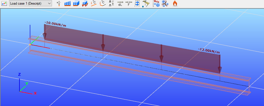
With section, load group, load case, member creation and all parameters:
LOAD_SECTION_LIBRARY Sec_ID1 "IPE 200"

CREATE LG_ID1 LoadGroup
Name "Permanent (Descript)"
LoadGroupType LGType_EN_P

CREATE LCase_ID1 LoadCase
Name "Load case 1 (Descript)"
LoadGroupID LG_ID1

CREATE Mem_ID1 Structural_member "IPE 200"
0 0 0
3000 0 0

CREATE LLoad_ID1 MemberForce LCase_ID1 Mem_ID1 local
0 1
200 400
0 0 -10
0 0 -12
EccType EccType_TM
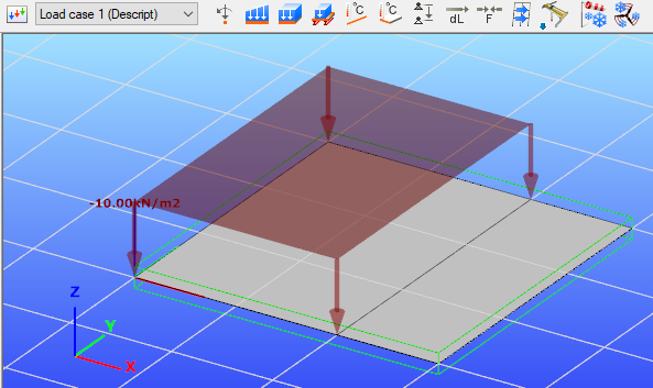
Surface load (uniform)
This command is analogous with the surface load creation dialogue with the uniform tab chosen in Consteel:
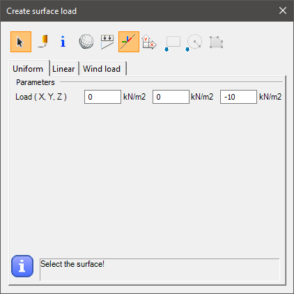
Syntax
CREATE PlateForce_Uniform [Load case ID] [Surface ID] [Coordinate system]
[Fx] [Fy] [Fz]
[x1] [y1] [z1]
[x2] [y2] [z2]
[x3] [y3] [z3]
etc.
Command parameters
| Command parameter | Assignment | Value format | Input options |
|---|---|---|---|
| Object ID | Required | String | Local, variable |
| Load case ID | Required | Load case name or ID | Local, variable |
| Surface ID | Required | Member name or ID | Local, variable |
| Coordinate system | Optional | Predefined string | Local, variable |
| Fx, Fy, Fz | Required | Numerical | Local, variable |
| xi, yi, zi | Optional | Numerical | Local, variable |
Object ID:
A string of characters that is used to identify the object that is being created.
Load case ID:
ID of the load case that will contain the load. The accepted input is either a load case ID or the name of a load case with this syntax: "NAME: [Load case name]"
Surface ID:
ID of the Surface to which the load will be attached. The accepted input is either a surface ID or the name of the surface with this syntax: "NAME: [Surface name]"
Coordinate system:
With this parameter it can be specified which coordinate system to use for the load definition. If unspecified the default is the global coordinate system. If specified, the only accepted input is: "local".
Fx, Fy, Fz:
Force components of the uniform surface load.
xi, yi, zi:
Coordinates of the corner points of the area where the surface load will be applied on the selected surface. If none is given, then the load will be applied on the entire surface. Otherwise at least 3 corner points have to be given.
Sample code
Command only: (minimal parameters)
CREATE SLoad_ID1 PlateForce_Uniform LCase_ID1 PlateID1
0 0 -10
With load group, load case, plate creation and all parameters:
CREATE LG_ID1 LoadGroup
Name "Permanent (Descript)"
LoadGroupType LGType_EN_P

CREATE LCase_ID1 LoadCase
Name "Load case 1 (Descript)"
LoadGroupID LG_ID1

CREATE Plate_ID1 Structural_Plate "C25/30 EN 1992-1-1:2010" 200
0 0 0
3000 0 0
3000 3000 0
0 3000 0

CREATE SLoad_ID1 PlateForce_Uniform LCase_ID1 Plate_ID1 local
0 0 -10
0 0 0
2000 0 0
2000 3000 0
0 3000 0
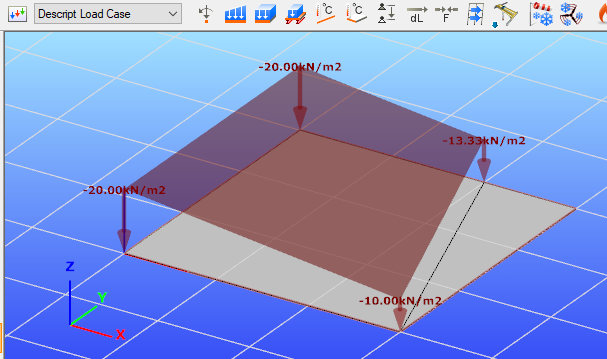
Surface load (linear)
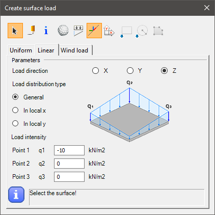
This command is analogous with the surface load creation dialogue with the linear tab chosen in Consteel:
Syntax
CREATE [Object ID] PlateForce_Linear [Load case ID] [Surface ID] [Coordinate system]
LoadDirection [Load direction]
DistributionType [Distribution type]
[q1x] [q1y] [q1z] [q1]
[q2x] [q2y] [q2z] [q2]
[q3x] [q3y] [q3z] [q3]
[x1] [y1] [z1]
[x2] [y2] [z2]
[x3] [y3] [z3]
etc.
Command parameters
| Command parameter | Assignment | Value format | Input options |
|---|---|---|---|
| Object ID | Required | String | Local, variable |
| Load case ID | Required | Load case name or ID | Local, variable |
| Surface ID | Required | Member name or ID | Local, variable |
| Coordinate system | Optional | Predefined string | Local, variable |
| Load direction | Required | Predefined strings | Local, variable |
| Distribution type | Required | Predefined strings | Local, variable |
| qix, qiy, qiz | Required | Numerical | Local, variable |
| q1, q2, q3 | Required | Numerical | Local, variable |
| xi, yi, zi | Optional | Numerical | Local, variable |
Object ID:
A string of characters that is used to identify the object that is being created.
Load case ID:
ID of the load case that will contain the load. The accepted input is either a load case ID or the name of a load case with this syntax: "NAME: [Load case name]"
Surface ID:
ID of the Surface to which the load will be attached. The accepted input is either a surface ID or the name of the surface with this syntax: "NAME: [Surface name]"
Coordinate system:
With this parameter it can be specified which coordinate system to use for the load definition. If unspecified the default is the global coordinate system. If specified, the only accepted input is: "local".
Load direction:
Direction of the surface load. Only 1 load direction can be chosen for 1 CREATE PlateForce_Linear command. The load direction is defined in the given coordinate system (local or global).
Available load directions:- x
- y
- z
Distribution type:
Type of the load distribution.
Available distribution types:- General → In this case the slope of the linear distribution is in a general direction, therefore 3 intensity points have to be defined (q1, q2, q3)
- x → In this case the slope of the linear distribution is parallel with the local x direction, therefore 2 intensity points have to be defined (q1, q2)
- y → In this case the slope of the linear distribution is parallel with the local y direction, therefore 2 intensity points have to be defined (q1, q2)
qix, qiy, qiz:
Coordinates for the load intensity points.
q1, q2, q3:
Load intensities at the given points.
xi, yi, zi:
Coordinates of the corner points of the area where the surface load will be applied on the selected surface. If none is given, then the load will be applied on the entire surface. Otherwise at least 3 corner points have to be given.
Sample code
Command only: (minimal parameters, general distribution)
CREATE PF_ID1 PlateForce_Linear LC01 SPID1
LoadDirection z
DistributionType General
3000 0 0 0
3000 3000 0 -10
0 3000 0 -20
With load group, load case, plate creation and all parameters:
CREATE SP_ID1 Structural_Plate "S 235 EN 10025-2" 16 50
0 0 0
3000 0 0
3000 3000 0
0 3000 0

CREATE LG_01 LoadGroup
Name "Descript Load Group"
LoadGroupType "LGType_EN_P"

CREATE LC_01 LoadCase
Name "Descript Load Case"
LoadGroupID LG_01

CREATE PF_ID1 PlateForce_Linear LC_01 SP_ID1 local
LoadDirection z
DistributionType x
0 0 0 -20
3000 0 0 -10
0 0 0
3000 0 0
2000 3000 0
0 3000 0
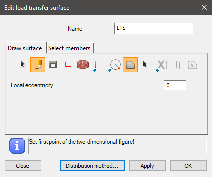
Load transfer surface
This command is analogous with the load transfer surface creation dialogue in Consteel, with the "draw polygon" option:
Syntax
CREATE [Object ID] LoadTransferSurface [Object name]
[x1] [y1] [z1]
[x2] [y2] [z2]
[x3] [y3] [z3]
etc.
Command parameters
| Command parameter | Assignment | Value format | Input options |
|---|---|---|---|
| Object ID | Required | String | Local, variable |
| Object name | Required | String | Local, variable |
| xi, yi, zi | Required | Numerical | Local, variable |
Object ID:
A string of characters that is used to identify the object that is being created.
Object name:
Name of the load transfer surface.
xi, yi, zi:
Coordinates of the corner points of the area where the load transfer surface will be. At least 3 corner points have to be given.
Sample code
CREATE LTS_ID1 LoadTransferSurface "LTS 1"
0 0 0
3000 0 0
3000 3000 0
0 3000 0
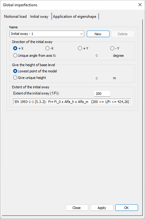
Initial sway
This command is analogous with the iitial sway tab of the global imperfections dialogue in Consteel:
Syntax
CREATE [Object ID] InitialSway [Direction] [Bottom height] [Sway denominator]
Name [Object Name]
Command parameters
| Command parameter | Assignment | Value format | Input options |
|---|---|---|---|
| Object ID | Required | String | Local, variable |
| Direction | Required | Predefined strings or numerical | Local, variable |
| Bottom height | Required | Predefined strings or numerical | Local, variable |
| Sway denominator | Required | Numerical | Local, variable |
| Object name | Optional | String | Local, variable |
Object ID:
A string of characters that is used to identify the object that is being created.
Direction:
Direction of the initial sway.
Available inputs:- +X -> angle = 0
- -X -> angle = 180
- +Y -> angle = 270
- -Y -> angle = 90
- [Number] -> angle = [Number] (unique angle from axis "x")
Bottom height:
Height of base level.
Available inputs:- BottomNode -> BaseHeight = h of bot node
- [Number] -> BaseHeight = [Number] (unique height)
Sway denominator:
Extent of the initial sway (1/φi).
Object name:
Name of the initial sway.
Sample code
Command only: (minimal parameters)
CREATE InitSway_ID1 InitialSway +X BottomNode 200
Command only: (all parameters)
CREATE InitSway_ID1 InitialSway -X BottomNode 200
Name "Init Sway -x (Descript)"
Mass group
This command is analogous with the mass group creation button in Consteel:
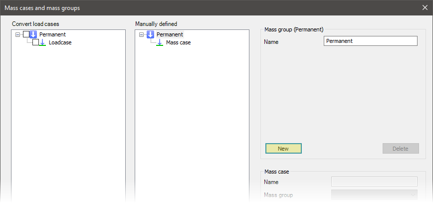
Syntax
CREATE [Object ID] MassGroup
Name [Object name]
MassGroupType [Mass group type]
Command parameters
| Command parameter | Assignment | Value format | Input options |
|---|---|---|---|
| Object ID | Required | String | Local, variable |
| Object name | Optional | String | Local, variable |
| Mass group type | Required | Predefined strings | Local, variable |
Object ID:
A string of characters that is used to identify the object that is being created.
Object name:
Name of the mass group.
Mass group type:
Type of the mass group.
Available mass group types:| Mass group type name | Mass group type |
|---|---|
| Permanent | MGType_EN_P |
| Variable | MGType_EN_T |
| Snow | MGType_EN_S |
Sample code
CREATE MG_ID1 MassGroup
Name "Mass group (Descript)"
MassGroupType MGType_EN_P
Mass case
This command is analogous with the mass case creation button in Consteel:
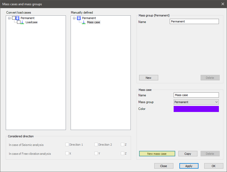
Syntax
CREATE [Object ID] MassCase
Name [Object name]
MassGroupID [Mass group ID]
SeismicDirection [Seismic direction]
FreeVibrationDirection [Free vibration direction]
Command parameters
| Command parameter | Assignment | Value format | Input options |
|---|---|---|---|
| Object ID | Required | String | Local, variable |
| Object name | Optional | String | Local, variable |
| Mass group ID | Required | Mass group name or ID | Local, variable |
| Seismic direction | Optional | Predefined strings | Local, variable |
| Free vibration direction | Optional | Predefined strings | Local, variable |
Object ID:
A string of characters that is used to identify the object that is being created.
Object name:
Name of the mass case. If not specified the default name is: "MassCase".
Mass group ID:
ID of the mass group that will contain the created mass case. The accepted input is either a mass group ID or the name of a mass group with this syntax: "NAME: [Mass group name]"
Seismic direction:
Controls the consideration of "z" direction in seismic analysis.
Available inputs:- 0 (default)
- z
Free vibration direction:
Controls the consideration of masses in directions for free vibration analysis.
Available inputs:- x
- y
- z
- x,y
- x,z
- y,z
- x,y,z (default)
Sample code
Command only: (minimal parameters)
CREATE MC_ID1 MassCase
MassGroupID MG_ID1
With mass group creation and all parameters:
CREATE MG_ID1 MassGroup
Name "Mass group (Descript)"
MassGroupType MGType_EN_P

CREATE MC_ID1 MassCase
Name "Mass case (Descript)"
MassGroupID MG_ID1
SeismicDirection 0
FreeVibrationDirection x,y,z
Mass combination
This command is analogous with the mass combination creation button in Consteel:
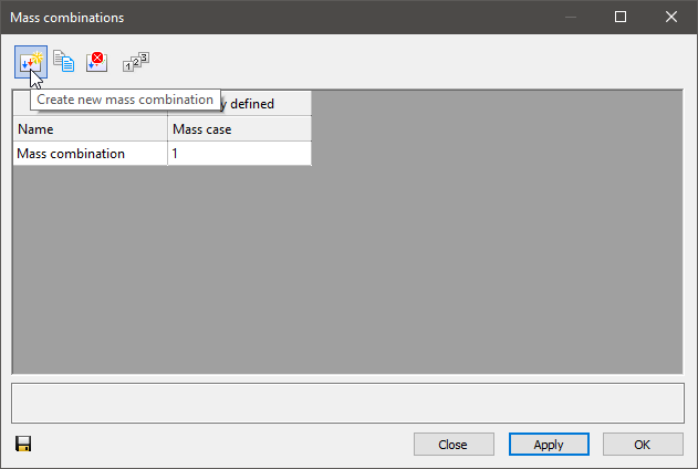
Syntax
CREATE [Object ID] MassCombination
Name [Object name]
[Mass case ID 1] [Mass case combination factor 1]
[Mass case ID 2] [Mass case combination factor 2]
etc.
Command parameters
| Command parameter | Assignment | Value format | Input options |
|---|---|---|---|
| Object ID | Required | String | Local, variable |
| Object name | Optional | String | Local, variable |
| Mass case IDs | Optional | Mass case name or ID | Local, variable |
| Mass case combination factors | Optional | Numerical | Local, variable |
Object ID:
A string of characters that is used to identify the object that is being created.
Object name:
Name of the mass combination. If not specified, the default name is: Load combination1.
Mass case IDs:
ID of mass cases for which combination factors will be specified. The accepted input is either a mass case ID or the name of a mass case with this syntax: "NAME: [Mass case name]"
Mass case combination factors:
Combination factors assigned to mass cases in the same row.
Sample code
Command only: (minimal parameters)
CREATE MComb_ID1 MassCombination
"NAME: Mass case" 1
With mass group, mass case creation and all parameters:
CREATE MG_ID1 MassGroup
Name "Mass group (Descript)"
MassGroupType MGType_EN_P

CREATE MC_ID1 MassCase
MassGroupID MG_ID1

CREATE MComb_ID1 MassCombination
Name "Mass combination (Descript)"
MC_ID1 1
Point mass
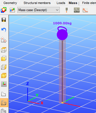
This command is analogous with the node mass creation dialogue in Consteel:
Syntax
CREATE [Object ID] NodeMass [Mass case ID] [Member ID]
[x] [y] [z]
[Mass]
Command parameters
| Command parameter | Assignment | Value format | Input options |
|---|---|---|---|
| Object ID | Required | String | Local, variable |
| Mass case ID | Required | Mass case name or ID | Local, variable |
| Member ID | Required | Member name or ID | Local, variable |
| x, y, z | Required | Numerical | Local, variable |
| Mass | Required | Numerical | Local, variable |
Object ID:
A string of characters that is used to identify the object that is being created.
Mass case ID:
ID of the mass case that will contain the mass. The accepted input is either a mass case ID or the name of a mass case with this syntax: "NAME: [Mass case name]"
Member ID:
ID of the member to which the load will be attached. The accepted input is either a member ID or the name of the member with this syntax: "NAME: [Member name]"
x, y, z:
Coordinates of the application point of the mass.
Mass:
Mass in [kg].
Sample code
Command only: (minimal parameters)
CREATE PMass_ID1 NodeMass MC_ID1 Mem_ID1
0 0 3000
1000
With mass group, mass case, member creation and all parameters:
LOAD_SECTION_LIBRARY section "HEA 200"

CREATE MG_ID1 MassGroup
Name "Mass group (Descript)"
MassGroupType MGType_EN_P

CREATE MC_ID1 MassCase
Name "Mass case (Descript)"
MassGroupID MG_ID1
SeismicDirection 0
FreeVibrationDirection x,y,z

CREATE Mem_ID1 Structural_Member "HEA 200"
0 0 0
0 0 3000

CREATE PMass_ID1 NodeMass MC_ID1 Mem_ID1
0 0 3000
1000
Portion
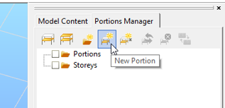
This command is analogous with the portion creation button in Consteel:
Syntax
CREATE [Object ID] Portion [Object name] [Content array]
CornerType [Corner type]
Command parameters
| Command parameter | Assignment | Value format | Input options |
|---|---|---|---|
| Object ID | Required | String | Local, variable |
| Object name | Required | String | Local, variable |
| Content array | Required | Object ID(s) | Array |
| Corner type | Optional | Predefined strings | Local, variable |
Object ID:
A string of characters that is used to identify the object that is being created.
Object name:
Name of the portion.
Content array:
The name of the array that contains the IDs of the objects that will be part of the created portion. This array substitutes the manual object selection that is necessary before the portion creation in Consteel. The object IDs have to be collected and put into an array before the execution of this command.
Corner type:
Corner type of the portion. This setting can be accessed from the frame corner wizard dialogue in the Consteel UI. The definition of this parameter also switches on frame corner functionality, which can also be controlled by the FRAME_CORNER command in Descript.
Available input options:- Warping_NotSet
- Warping_Reverse
- Warping_Equal
- Warping_Zero
The definition of this parameter is optional. Default value: Warping_NotSet.
Sample code
Command only: (minimal parameters)
CREATE Portion_ID1 portion "Portion 1 (Descript)" ObjIDs_to_portion
Command only: (all parameters)
CREATE Portion_ID1 portion "Portion 1 (Descript)" ObjIDs_to_portion
CornerType Warping_Reverse
With object and array creation:
LOAD_SECTION_LIBRARY Sec_ID1 "HEA 200"

CREATE Mem_ID1 Structural_Member "HEA 200"
0 0 0
0 0 1000
Name "Structural Member 1"

CREATE Mem_ID2 Structural_Member "HEA 200"
0 0 1000
0 1000 1000
Name "Structural Member 2"

CREATE Mem_ID3 Structural_Member "HEA 200"
0 0 1000
0 1000 0
Name "Structural Member 3"

ARRAY_CREATE ObjIDs_to_portion
ARRAY_SET ObjIDs_to_portion 0 Mem_ID1
ARRAY_SET ObjIDs_to_portion 1 Mem_ID2

CREATE Portion_ID1 portion "Portion 1 (Descript)" ObjIDs_to_portion


